


7
(a) Installed the appliance when gas is available at the time of installation; or
(b) Makes gas available to the appliance if gas was not available at the time of installation
As per
AS/NZS5601.1
, clause 6.11.3, the commissioning of this appliance shall take
full account of special
design features, the manufa
cturer’s instructions and the appliance safety requirements
.
As per
AS/NZS5601.1
, clause 6.11.4, the commission of this appliance shall include all of the following;
(a)
Testing and purging
of the appliance and installation as appropriate.
(b) Checks to ensure the appliance is in
safe working order
.
(c) Ignition of each
burner
of the appliance and where necessary adjustment, in accordance with the
manufacturer’s instructions.
(d) Testing of
flue
performance.
(e) Testing of all
safety devices
for correct operation.
(f)
Instruction
of the consumer, where available, on the safe and correct operation of the appliance
and any auxiliary equipment.
(g) Handing of the appliance
operating instructions
to the consumer, or if the consumer is not present,
leaving the instructions in a suitable location on the premises.
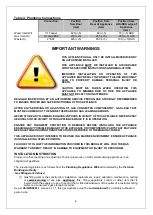
Installation Instructions
Regulations
The appliance
must
be installed only by authorised
person and in accordance with the manufacturer’s
installation instructions, local gas fitting regulations, municipal building codes, AS 5601
– Gas Installations
and any other health and safety regulations, local authority, gas, electrical any other statutory regulations.
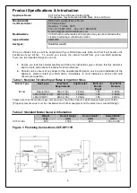
Data Label
The data label is located either on the front of the appliance or behind the door. This appliance is suitable for
Natural Gas and LPG. Please ensure that the gas supply matches the Data Label ensuring that the gas
supply is correct for the appliance being installed and that adequate supply pressure and volume is available
– refer to appliance data plate for MJ/h consumption, injector sizes of main burners/pilots, etc.
Ventilation
This appliance should be installed under an extraction hood (with a clearance of 1350mm to the grease
filter). Ventilation must be in accordance with AS/NZ5601 -
Gas
Installations. In general, the appliance
should have adequate ventilation for complete combustion of gas, proper flueing and to maintain
temperature of immediate surroundings within safe limits. It is
mandatory
that this appliance is installed
under an extraction hood.
The appliance shall be installed with an exhaust system comprising a hood and duct system. The hood shall
be made of a material which is impervious to fat, grease and vapour. It shall be constructed so it can be
readily and efficiently cleaned. Its inside faces shall be smooth and free of obstructions and all joints shall be
grease tight.
The hood shall be located so as to effectively ventilate the wok and shall extend at least 150 mm beyond the
perimeter of the wok. The exhaust duct system shall be adequately sized and shall not get connected to any
other ventilating or exhaust system.
As suitable grease trap shall be provided to prevent grease vapour entering the exhaust system and shall be
located to avoid constituting a fire hazard and be readily accessible for regular cleaning.
Unless adequately protected a hood and a duct shall be fitted at least 450 mm from any combustible material
and so that the lower edge of the grease filter is no less than 1.35 meters above the cooking surface.
(please refer to AS/NZS 5601 clause 6.10.2.2 to verify clearances for ventilation
.)
B&S units can be installed in a domestic environment provided the installation is strictly in accordance
with the manufacturer’s instructions and as per the AS/NZS5601.1 (please refer to the latest version
when released). The installation of the unit must comply with clauses 6.2.4, 6.10.2 and 6.10.1.15 and an


