background image

 19 

Mobile Plate Dispenser 

OPERATING INSTRUCTIONS


–

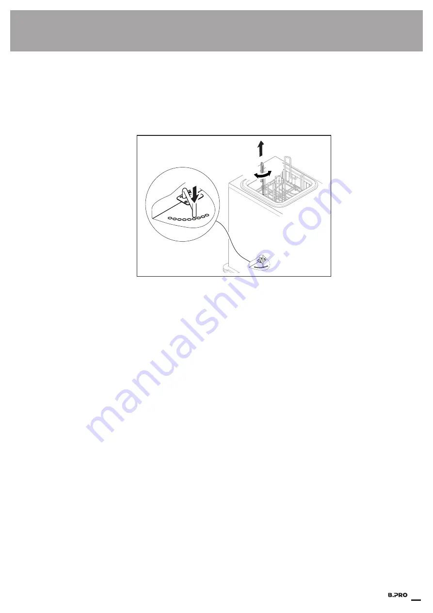
Pull the guide rod upward (1.).

4.

1.

2.

3.


–

Turn the guide rod toward the centre of the tube (2.) if the diameter is to be reduced 
– or – 
Turn the guide rod toward the housing cover (3.) if the diameter is to be increased.


–

Lower the guide rod (4.) and insert it in the corresponding guide hole in the unit bottom.


–

Lock the guide rod's transport securing device 


L

The distribution height of stacked items is adjusted using springs, which are used to mount 
the stacking platform at the top of the unit housing.


L

Individual springs can be hooked/unhooked to adjust the distribution height of stacked items 
if necessary.


L

The unit is supplied from the factory with fully hooked springs. We recommend testing the 
distribution height of stacked items using this spring setting and making adjustments if ne-
cessary. 


)

If a different type of stacked item is to be stacked at a later time and it is necessary to change 
the distribution height of stacked items, either unhooked springs must be hooked in or additi-
onal springs unhooked.


)

The distribution height of stacked items is correctly adjusted when the top plate is positioned 
above the unit cover.


–

Place 11 plates on the stacking platform.


–

If the top plate does not extend above the upper side of the unit or several plates extend abo-
ve the upper side of the unit, remove all plates and change the spring setting.


ª

Section "Setting the distribution height of stacked items"


–

Retest the distribution height of stacked items after changing the spring setting.


–

If necessary, repeat the spring setting change and testing of the distribution height of stacked 
items until the correct setting is achieved.

Testing distribution height 

of stacked items

Summary of Contents for TS-H1

Page 1: ...Translation of the original operating instructions PLATE DISPENSER TS H1 H2 UH2...

Page 2: ...pter section or external document 9 Requirement which must be fulfilled before the subsequent steps can be carried out Action or activity which must be carried out Unit model XYZ A section identified...

Page 3: ...tes for operation 18 Initial start up 18 Adjusting guide rods to the plate diameter 18 Testing distribution height of stacked items 19 Setting the distribution height of stacked items 20 Mounting reta...

Page 4: ...g plate stacking well 37 Cleaning cleaning drawers 39 Maintenance Having unit regularly maintained 40 Checking castor brakes 40 Having periodical electrical safety inspection carried out 40 Checking c...

Page 5: ...5 Mobile Plate Dispenser OPERATING INSTRUCTIONS Standards guidelines rules regulations Standards 48 Directives for CE marking EU declaration of conformity 48 Rules regulations 48...

Page 6: ...6 Mobile Plate Dispenser OPERATING INSTRUCTIONS...

Page 7: ...tipping The unit must not be used to transport or store dangerous or toxic substances liquids Environment The unit may be used when the ambient temperature is between 15 C and 38 C and at nor mal hum...

Page 8: ...ical capillary tube thermostat The desired setpoint temperature in the unit can be set continuously via a rotary knob below the push handle The setting 7 corresponds to a temperature of about 60 C The...

Page 9: ...be read carefully prior to commissioning The owner is responsible for ensuring that all users have read these instructions before using the unit Store these operating instructions in a location which...

Page 10: ...loves when handling hot guide rods Distribution height of stacked items The distribution height of stacked items must be adjusted to current needs when commissio ning If the stacking platform is set t...

Page 11: ...et outlet may become damaged Only unplug by pulling on the mains plug housing General Information The user must be aware of the hazards that the unit presents and be able to assess them The unit may o...

Page 12: ...th a diameter between 180 and 330 mm and square ones measuring between 180 x 180 and 280 x 280 mm may be used in the plate dispenser with 4 guide rods for each stacking well If smaller plates are used...

Page 13: ...p and interior and the cleaning drawer optional and objects dishes in the unit be come hot during operation up to about 110 C and can cause burns Protection e g with pot holders or protective gloves m...

Page 14: ...or recesses Disconnecting the mains plug Insert and remove mains plug only while unit is switched off as otherwise the unit electrical sys tem and the mains socket outlet can be damaged Only unplug th...

Page 15: ...lectrical safety inspection at least once every six months in accordance with the DIN VDE 0702 series of standards Connection cable and mains plug Check the connection cable and mains plug for mechani...

Page 16: ...ards guidelines and safety regulations The owner is responsible for compliance with the applicable standards guidelines and safety regulations The unit is fitted with a rating plate The warranty is vo...

Page 17: ...ed correctly The unit recipient must provide suitable proof if transport damage is reported at a later point in time The scope of delivery contains the following as standard Unit Retaining clip for ho...

Page 18: ...available mains voltage or frequency Before connecting make sure that the mains voltage and mains frequency on the rating plate correspond with those for the mains socket outlet Ensure that no object...

Page 19: ...t of stacked items using this spring setting and making adjustments if ne cessary If a different type of stacked item is to be stacked at a later time and it is necessary to change the distribution he...

Page 20: ...e sharp start of the spring can cause injuries to arms hands and fingers if fitted incorrectly When fitting the springs you must ensure that the start of the spring on both sides does not point to the...

Page 21: ...o mount two PC hooded covers or one EPP hooded cover 1 2 1 Position for mounting PC hooded covers 2 Position for mounting EPP hooded cover Slide the retaining tongue into the desired mounting from beh...

Page 22: ...The unit s electrical system may suffer damage if the unit is not designed for the available mains voltage or frequency Before connecting make sure that the mains voltage and mains frequency on the ra...

Page 23: ...ing signal optional 5 Retaining clip for hooded cover 6 Push handle 7 Operating panel with switch and temperature control 8 Mains cable 9 Cleaning drawer optional 10 Mains plug retainer 11 Steering ca...

Page 24: ...empera ture setting except the following When the temperature in the unit climbs above 60 C the operating personnel must perform suitable safety measures to ensure that no damage arises To prevent bur...

Page 25: ...eir fingers on dishes or the top of the unit B PRO recommends carefully testing the temperature with your hand about 45 minutes after switching on and adjusting the temperature setting if necessary If...

Page 26: ...he synthetic di shes can be damaged The upper weight limits specified in the technical data may not be exceeded when loading 9 Distribution height of stacked items set correctly 9 Guide rods adapted t...

Page 27: ...retaining clip 2 1 Turn hooded cover slightly upward at bottom 1 and take out of retaining clip toward front 2 Lay EPP hooded cover in retaining clip 2 3 1 Turn hooded cover slightly upward at bottom...

Page 28: ...elf with a maximum surface load of 25 kg Folding up fold down shelf Lift the fold down shelf somewhat approx 30 until it is above the horizontal 1 1 2 Allow the fold down shelf to glide downward towar...

Page 29: ...9 2 people Unit model with fold down shelf 9 The fold down shelf is now folded down Caution Be careful not to pinch your foot The foot can be pinched and injured when the castor brakes are released a...

Page 30: ...immediately after operation If the unit is being pushed by two people and one of them touches the unit top with his her hands they can be burned Always wear gloves while touching the hot unit top when...

Page 31: ...s the unit must be positioned in such a way that unautho rised persons are not able to adjust the temperature control The unit side with the tempera ture control can be turned to a wall for example Wa...

Page 32: ...late Dispenser OPERATING INSTRUCTIONS Shutting down Switching off unit with the On Off switch The operation indicator goes out Unplug the mains plug and insert it into the mains plug retainer Shutting...

Page 33: ...ical system is defective Notify a centre authorised to carry out repairs Chapter Repairs Cause Measure Overload protection has been triggered Notify a centre authorised to carry out repairs Chapter Re...

Page 34: ...ndling care Cause Measure Damage during transport change of lo cation or other external influences Shut down unit Chapter Shutting down Secure the unit to ensure it cannot be started up accidentally N...

Page 35: ...h as steel or iron Contact with iron such as iron contained in steel wool chips from pipelines or water contai ning iron particles Contact with the aforementioned substances must be avoided to maintai...

Page 36: ...B PRO microfibre cleaning cloth use with water only Residue stains especially grease splashes and accumulations of grease can be removed with a 30 soft soap solution and the help of a brush with synt...

Page 37: ...If mineral or even metallic dust needs to be removed during cleaning you must continuously rinse out cleaning utensils such as brushes and microfibre cloths to ensure that dust particles leave no mar...

Page 38: ...of crushing due to trapped hands If the stacking well is held outside on the stacking well flange when inserting in the unit body there is a danger of fingers becoming trapped and injured when loweri...

Page 39: ...in the pushing direction Both guide rails are each provided with a pull out stop which prevents the cleaning drawer from slipping out accidentally Lift the cleaning drawer 1 slightly at the front 1 un...

Page 40: ...The castor brakes must be checked to ensure that they are effective every time the unit is mo ved to a new location Lock castor brakes Try to move the unit do not use force If brakes do not lock effec...

Page 41: ...59 75038 Oberderdingen Germany Made in Germany Order V Hz kW Item No 1 2 3 4 5 IP X 1 Article number 2 Date of manufacture 3 Model description 4 Date of manufacture 5 Production order number Defective...

Page 42: ...Plate Dispenser OPERATING INSTRUCTIONS B PRO GmbH Flehinger Str 59 75038 Oberderdingen Phone 49 0 7045 44 81416 Fax 49 0 7045 44 81508 E mail service bpro solutions com Internet www bpro solutions co...

Page 43: ...rs the symbol on the left to indicate such contents in compliance with EN 50419 Marking of electrical and electronic equipment in accordance with Article 15 2 of Directive 2012 19 EU WEEE You must als...

Page 44: ...erior dimensions in mm L x W x H including EPP hooded cover TS H1 680 x 520 x 1030 680 x 520 x 1120 TS H2 1075 x 520 x 1030 1075 x 520 x 1120 TS UH2 1115 x 520 x 1030 1115 x 520 x 1120 Model Clear dim...

Page 45: ...erature range unit interior 30 C to 110 C Connected loads Model Voltage Output maximum TS H1 220 to 240 V 50 to 60 Hz 0 9 kW TS H2 220 to 240 V 50 to 60 Hz 1 2 kW TS UH2 220 to 240 V 50 to 60 Hz 1 5 k...

Page 46: ...ATING INSTRUCTIONS Materials Unit body Stainless steel powder coated stainless steel panel polyamide polyethylene PC hooded cover Polycarbonate EPP hooded cover optional for TS H1 2 Polypropylene Guid...

Page 47: ...71 Article number 573 767 Article number See B PRO price list Article number 126 999 Article number 511 895 TS H1 18 33 plate dispenser TS H2 18 33 plate dispenser TS UH2 18 33 plate dispenser Operati...

Page 48: ...ctive 2014 35 EU Low Voltage Directive 2014 30 EU EMC Directive 2011 65 EU RoHS Directive 2014 68 EU Pressure Equipment Directive The following rules regulations German Employers Liability Insurance A...

Page 49: ...49 Mobile Plate Dispenser OPERATING INSTRUCTIONS...

Page 50: ...50 Mobile Plate Dispenser OPERATING INSTRUCTIONS...

Page 51: ...51 Mobile Plate Dispenser OPERATING INSTRUCTIONS...

Page 52: ...RO GmbH P O Box 13 10 75033 Oberderdingen GERMANY Phone 49 0 7045 44 81416 Fax 49 0 7045 44 81508 Email service bpro solutions com Internet www bpro solutions com Document No 154 630 en Version 4 0 10...

Reviews: