background image

13.  

MINI-P-PP-A-GH-FC - Connection

Connect the B.E.G. Controls MINI-P-PP-A-GH-FC 

sensor to the PP-A-J or PP-1-J power pack using the 

sensor’s RJ12 connector.

RJ12

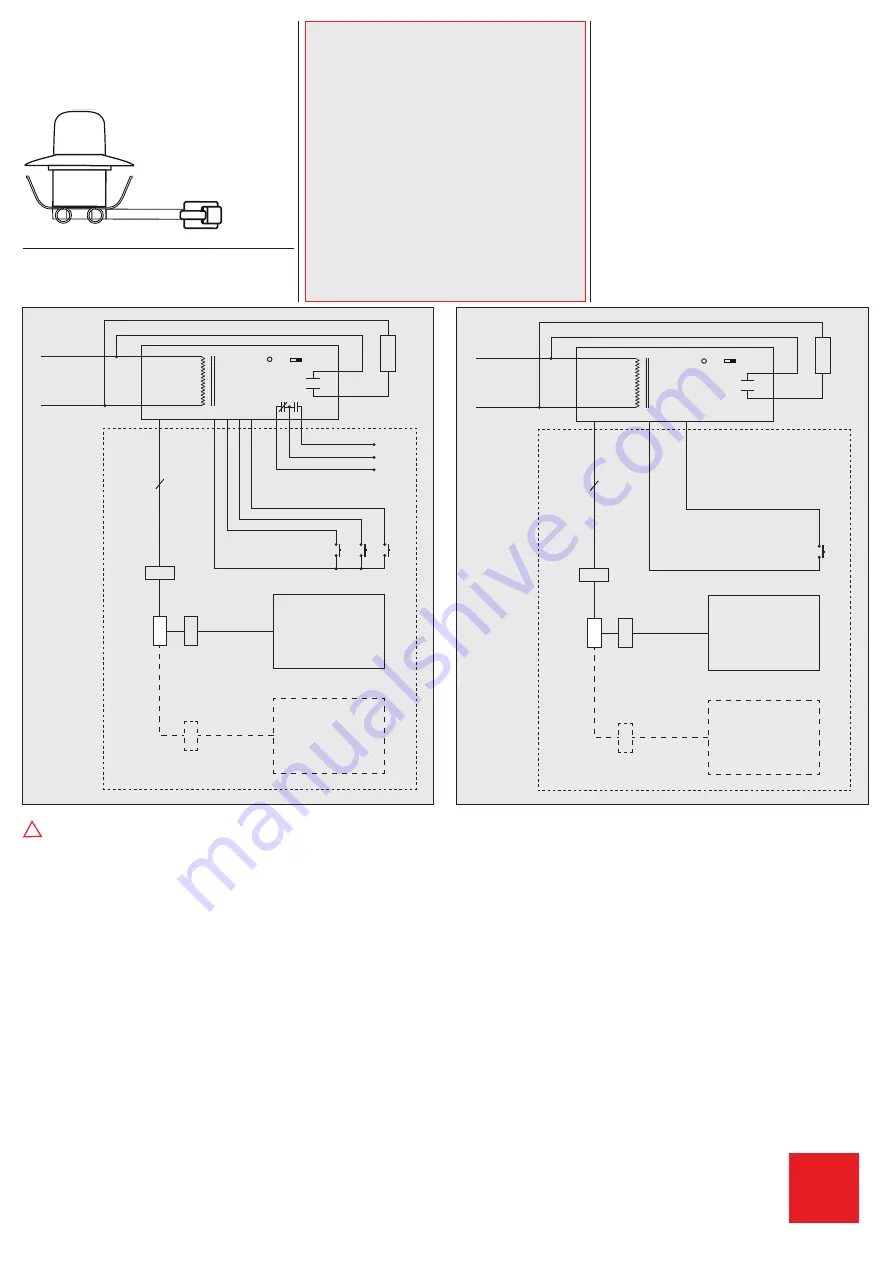
14.  Wiring diagrams with Power 

pack PP-A-J and PP-1-J

Standard mode with Primary/Secondary 

!


Secondary sensors and primary sensor must be 

connected to the same power pack.

15. Reset of the detector

Following settings can only be changed using the 

B.E.G. Controls IR-Adapter for smartphones and 

app.If the configuration settings lock is activated,  

the detector can be released again as follows:

•  Disconnect and reconnect sensor from power pack

•  Let sensor initialize for about 31 to 59 seconds  

•  Disconnect sensor from power pack

•  Connect sensor back to power pack and wait 

for the sensor to go through self-testing

•  Press the unlock button

Pressing the „RESET“ button on the remote control, 

in programming open mode, will delete all of the 

values set by the remote control. Sensor settings 

will be set back to factory settings. 50 fc (500 Lux), 

10 minute timeout.

B.E.G.

 Controls


277 Highway 74 N, Suite 319 

Peachtree City, GA 30269 

Phone: 770-349-6341 

Email: [email protected]

MAN 8

88

6-010

916_1

Controls

B.E.G.

Hot

White

Black

Neutral

Brown

Orange

Gray

Red

Y / B

Y / R

HVAC 

Load 

PB 

PB  PB 

Power Pack

Switch

PP-A-J

LED Switch

RJ 12

RJ 12

RJ 12

6

S

Secondary

P

Primary

All Off

 HVAC Load 

Red

Red

120 - 277 VAC

24 VDC

max. 200 mA

RJ12 male 

to dual 

RJ12 

female 

splitter

Hot

White

Black

Neutral

Gray

Red

Load 

PB 

Power Pack

Switch

PP-1-J

LED Switch

RJ 12

RJ 12

RJ 12

6

S

Secondary

P

Primary

Load


Red

Red

120 - 277 VAC

24 VDC

max. 200 mA

RJ12 male 

to dual 

RJ12 

female 

splitter

Summary of Contents for MINI-P-PP-A-GH-FC

Page 1: ...eze spring clips through ceiling opening Sensor should clip securely into place See Figure When using primary and secondary devices please mount the primary device at the place with the least amount of natural light 5 Position LEDs LED 1 green red 6 Self test cycle Startup behavior When power is first applied the sensor enters an initial 60 second self test cycle During this time the device does n...

Page 2: ...to power pack and wait for the sensor to go through self testing Press the unlock button Pressing the RESET button on the remote control in programming open mode will delete all of the values set by the remote control Sensor settings will be set back to factory settings 50 fc 500 Lux 10 minute timeout B E G Controls 277 Highway 74 N Suite 319 Peachtree City GA 30269 Phone 770 349 6341 Email info b...

Page 3: ...ed in correctly Step 4 Please check that the Smartphone s loudness level is maximum in order to ensure a correct operation 2 Procedure to use the remote control app Start page Help To access the device selection page click on the three white horizontal lines in the upper left corner or swipe from left to right Device or remote control selection Select Remote controls Select IR MINI P Functions Dev...

Page 4: ...and send 3 Send multiple parameters at once You may want to apply the same parameter settings to more than just one MINI Primary sensor in this case you can use the Activate Deactivate function to select multiple commands The Send highlighted commands button will then send all selected parameters Please note that this is only applicable for open state functions The app will always send the Open de...

Reviews: