4
l
Cables
Except for 24 V AC models, use a power cable rated at 600 V or
more and 70 °C or higher.
For 24 V AC models, use a power cable rated at 60 V or more
and 70 °C or higher.
The auxiliary switch cable should be rated at a voltage sufficient
for the operating voltage and rated at 70 °C or higher.
For other signal lines, use cables rated at 60 V or more and
70 °C or higher.
l
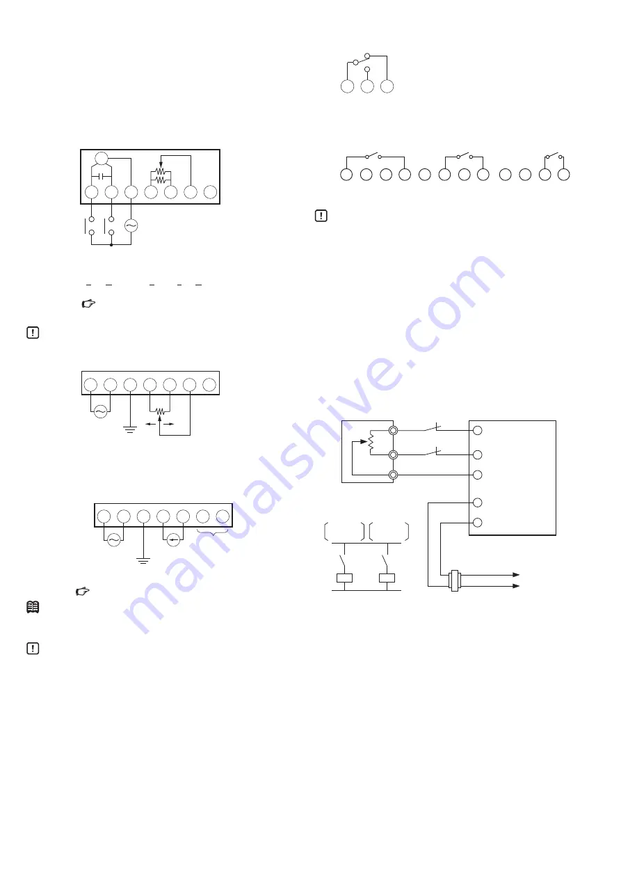
Relay contact input (ECM3000D and ECM3000F)
1
2
M
L
R
G
Y
T
3
4
5
6
7
Not used
*1
*2
*2
*2
L: counterclockwise (CCW) rotation
R: clockwise (CW) rotation
CW: Clockwise CCW:
Counterclockwise
*1. The supply voltage varies depending on the model.
MODEL SELECTION TABLE (page 2 )
*2. Terminals 4–6 of the ECM3000D are not used.
Handling Precautions
• The default setting for the output shaft is 0 % opening.
l
Potentiometer input (135 Ω) (ECM3000E)
1
2
W
24 V AC
F.G.
B
R
R
L
3
4
5
6
7
*
Not used
L: counterclockwise (CCW) rotation
R: clockwise (CW) rotation
* For details on TY9000, etc., contact the azbil Group.
l
4–20 mA input (ECM3000G)
1
2
*
4–20 mA DC
F. G.
+
−
3
4
5
6
7
Not used
* The supply voltage varies depending on the model.
MODEL SELECTION TABLE (page 2 )
Note
• The 4–20 mA input circuit is isolated from the power circuit
inside the device.
Handling Precautions
• During motor operation, in order to stop hunting (which
causes the controller’s internal relay to turn ON and OFF
excessively), change the parameters of the controller. For
example, set the derivative time (D) to 0 seconds, set a
wider dead band, etc.
If the internal relay operates excessively, the life of the
motor or the host controller relay will be shortened.
If frequent operation cannot be avoided, install an auxiliary
relay between the motor and controller.
• The feedback potentiometer of the ECM3000F is a com-
bination resistor consisting of two different resistors con-
nected in parallel.
Accordingly, the angle of rotation of the ECM3000F is pro-
portional not to the resistance of the feedback potentiom-
eter but to the voltage ratio between the potentiometer
terminals (T–G voltage or Y–G voltage).
The resistance of the feedback potentiometer cannot be
used to measure the angle of the motor rotation.
l
Auxiliary switch (up to 4)
A1
A2
A3
R
COM
L
L: counterclockwise (CCW) rotation
R: clockwise (CW) rotation
Note: The internal connections of switches B, C,
and D are the same as those of switch A.
Models with forced open/close function
have only auxiliary switches A and B.
l
Forced open/close input
(a) Forced fully closed (b) Forced fully open (c) Automatic operation
CCW CW CONT S
CCW CW CONT S
CCW CW CONT S
Handling Precautions
• Before shipment, terminals CONT and S are connected.
Disconnect these terminals if operation with the valve
forced fully open (or closed) is desired.
• Only one of terminals CCW, CW, and CONT can be con-
nected to terminal S. Multiple terminals cannot be con-
nected to terminal S.
• Be sure to connect non-voltage contacts to terminal S,
CONT, CW, or CCW of an ECM3000 model with a forced
open/close function. If 24 V AC is applied, the circuits will
fail.
• If the same signal is input to multiple control motors that
are connected in parallel, faulty operation may result.
The same contact signal cannot synchronize multiple
ECM3000 motors.
l
If the ECM3000E is used to fully open/close the valve
4
5
6
1
2
W
XO
W
B
R
Azbil Corporation's
L91 pressure regulator
Transformer
Power supply
ECM3000E
(resistance input of nominal 135 Ω)
Switch for
full open
XO
XC
100 % when XO is open
0 % when XC is open
Switch for
full close
XC
B
R
T
1
T
2
Note: Recommended contact rating for XO and XC
Material: Gold plating
Rated voltage: 15 V DC min.
Rated current: 100 mA


