


USER MANUAL
_
8
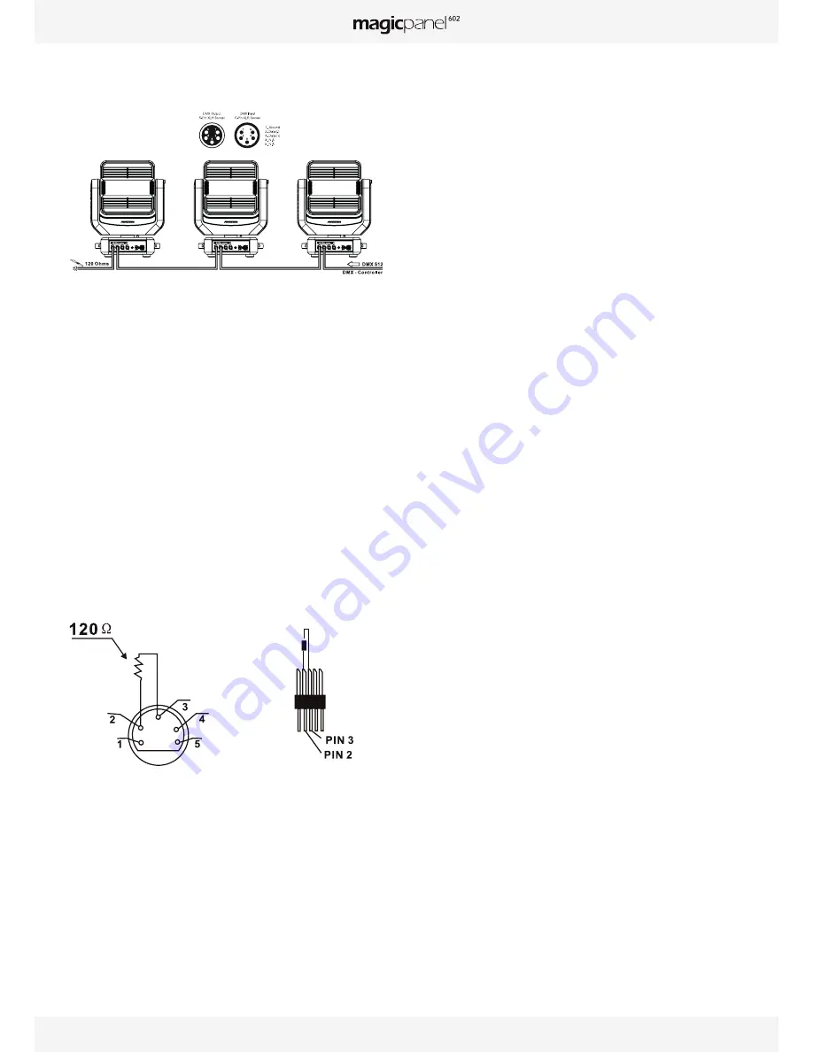
Refer to the following diagram:
Address 41 Address 21 Address 1
Warning:
To ensure maximum stability at a 100-120 VAC, no more than tow
luminaires should be connected together. A third luminaire should be
connected to another power source.
When the power voltage is 220-240 VAC, a maximum of five luminaires
can be connected together in this way. A sixth luminaire should be
connected to another power source.
DMX512 CONNECTION WITH TERMINATION PLUG
For installations where the DMX cable must extend over long distances,
or if it is located near areas with major electrical disturbance, it is
recommended to use a DMX termination plug. This helps prevent
luminaires from malfunctioning due to interference. The DMX termination
plug, composed simply of a male XLR input connector with a 120-Ohm
resistor, is soldered between pins 2 and 3. This plug must be connected
to the DMX output of the last luminaire in the chain.
Refer to the following diagram:
UsING DMX vIA ART-NET
To control the MagicPanel 602 DMX via ART-NET, the fixtures must be
interconnected with CAT5 RJ45 cable. Be careful to enter all necessary
information into the ART-NET universe being used and specify in the menu
that the MagicPanel 602 is controlled through ART-NET (see OPTION
DETAILS in the “OPTION” menu).
WARNING! The MagicPanel 602 can only read the first twelve universes of
an ART-NET packet. If you have more than 12 universes in your network,
you must use a configurable switch to filter each RJ45 output.
THE LUMINAIRE’s DMX ADDREss sETTING
All luminaires have a DMX start address correctly set when using a DMX
signal to control them. The DMX start address is the channel from which
the luminaire “listens” to the digital control information sent by the DMX
controller.
The start address must conform to the one recorded on the DMX controller
to run the luminaire. This address is the DMX value that appears on the
luminaire’s display. You can set the same address for all the luminaires,
or a group of them, but you can also set a different address for each
luminaire, as needed.
If you set the same address for all the luminaires, they will all “listen” from
the DMX channel that you have set. The orders sent by the DMX controller
will affect all luminaires at the same time.
If you set a different address per luminaire, each can be controlled
independently by the DMX controller. If, for instance, the fixtures are
preset in 20-channel DMX mode (required for full control), you will need to
adjust the DMX address for the luminaires as follows: The first unit with
DMX address 001, the second with DMX address 021 (20 + 1), the third
with DMX address 041 (20 + 21), etc.
InStructIonS For uSInG tHE WIrELESS
IntErnAL dmX SYStEm
1. REQUIRED HARDWARE
DMX512 controller, LumenRadio™ wireless transmitter, and MagicPanel
602 luminaires with wireless receivers.
2. WIRELESS INDICATOR – FIXTURE SCREEN
• Solid green: Connected to transmitter and receiving DMX data.
• Solid red: No connection to transmitter.
3. W-DMX IN THE FIXTURE MENU:
This part of the menu allows you to select if the unit will be controlled by
wireless DMX (See WDMX in OPTION DETAILS)
Choose the WDMX option in the “Signal Select” submenu under the
“OPTION” menu. The fixture will always return the DMX signal through
the XLR 5 output.
REST WDMX: Antenna – In the “Wireless DMX” submenu. This function
allows you to remove a luminaire from a wireless network, e.g., to pair it
with another transmitter.
4. CONFIGURING THE WIRELESS SYSTEM:
• Connect the transmitter to the DMX controller.
• The fixture’s indicator should default to red.
• Press the configuration button on the transmitter for 3 seconds. Wait
5-10 seconds for the pairing to occur. The “wireless” indicator on the
receiver fixture should be green.
• Once pairing is achieved, the receiver fixture retains the connection
Summary of Contents for magicpanel 602
Page 1: ...USER MANUAL V 3 2 ENGLISH VERSION 12 16 2014...
Page 2: ......
Page 19: ...USER MANUAL _ 19...
Page 20: ...www ayrton eu...


