


32
E
COnnECTing
imPOrTAnT: DiSCOnnECT THE nEg. mAin POWEr
CABlE FrOm yOUr CAr BATTEry BEFOrE Any
COnnECTiOn WOrk iS CArriED OUT!
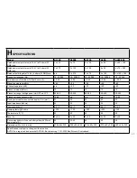
recommended Power Cable Cross-Sections and main
Fuse Values (for +12V and ground cable based on
5 m +12 V cable)
model
Cross-Section
main Fuse
A1390
20 mm
²
60 A
A2090
20 mm
²
60 A
A2190
20 mm
²
60 A
A490
20 mm
²
60 A
A480-250
20 mm
²
60 A
it is recommended to connect your amplifier according to
the following sequence:
1
Make sure your head-unit is turned off and the volume
control is in its minimum position.
2
RCA outputs of your head-unit to respective RCA
inputs of your amplifier (see „Connecting Diagrams“).
Sub pre-outs from head-unit should be fullrange signals
because lowpass pre-out signals always affect the filtering
electronics of amplifier! In case of doubt just 'double' a full-
range front or rear pre-out by using Y-adaptors.
3
Next step: Connect the remote lead
connection from
the head-unit to the amplifier.
4
Speaker cables to respective speakers or passive
crossovers. Make sure to maintain polarity! "+" to "+"
and "-" to "-".
For Mono 1-channel mode use of 4/2-channel models,
connect the two terminals "+" and "-" marked with
BRIDGE!
Min. impedance for bridged mode is 4 ohms!
5
Ground connection to chassis ground or negative battery
pole. If possible keep ground cable as short as possible
and make sure the chassis contact is well sanded, i.e. clean
from any paint, rust or dirt for lowest contact resistance.
6
+12 V power connection to positive battery pole. Do
not forget to install a main fuse within 20–30 cm of
car battery (fire hazard)!!!
Do not c12 V cable to battery before re-checking
every other connection on the amplifier!
Turn-on your head-unit keeping your volume at the lowest
setting. The green status LED on front of the amplifier heat
sink should light up now. If not, turn-off your head-unit
and re-check all wiring to and from the amplifier for mis-
sing or faulty connections.
Summary of Contents for A1390
Page 5: ...5 Anschlüsse Bedienungselemente A1390 q w e r t y u i o ...
Page 7: ...7 Anschlüsse Bedienungselemente A2090 A2190 q w e r t y u i o q w e r t y i o ...
Page 9: ...9 Anschlüsse Bedienungselemente A490 q w e r t y u i o ...
Page 11: ...11 Anschlüsse Bedienungselemente A480 250 q w e r t y u i o f g ...
Page 20: ...20 ...
Page 23: ...23 Connections Controls A1390 q w e r t y u i o ...
Page 25: ...25 Connections Controls A2090 2190 q w e r t y u i o q w e r t y i o ...
Page 27: ...27 Connections Controls AXTON A490 q w e r t y u i o ...
Page 29: ...29 Connections Controls A480 250 q w e r t y u i o f g ...
Page 38: ...38 ...
Page 41: ...41 Connections et réglages AXTON A1390 q w e r t y u i o ...
Page 43: ...43 Connections et réglages A2090 2190 43 q w e r t y u i o q w e r t y i o ...
Page 45: ...45 Connections et réglages AXTON A490 45 q w e r t y u i o ...
Page 47: ...47 Connections et réglages AXTON A480 250 q w e r t y u i o f g ...
Page 55: ...55 ...
Page 58: ......


