background image


Page 3 

                    1315 Directors Row Suite 107 Fort Wayne, IN 46808  

  (260)496-9668  

  www.atterotech.com 

2.2– Display and LED Status Indications 

The  C1  is equipped with an LED indicator below the rotary 
encoder.  The following chart indicates the available LED status 
information: 
 

LED State 

Status 

Slow Flashing 

White 

Identify function active 

Green 

If audio metering is enabled,  
the  audio level > -40 dBFS and < -20dFS 

Yellow 

If audio metering is enabled,  
The 

audio level ≥ 

-20 but < 3 

Red 

If audio metering is enabled,  
The 

audio level ≥ 3

 dBFS 

Blue 

Mute is active 

Flashing Blue 

Firmware Update  

Steady White 

Main Menu is active 

Quick Flashing 

White 

A menu selection has been executed 


On power up, the C1 will present a splash screen while acquiring 
an IP address.


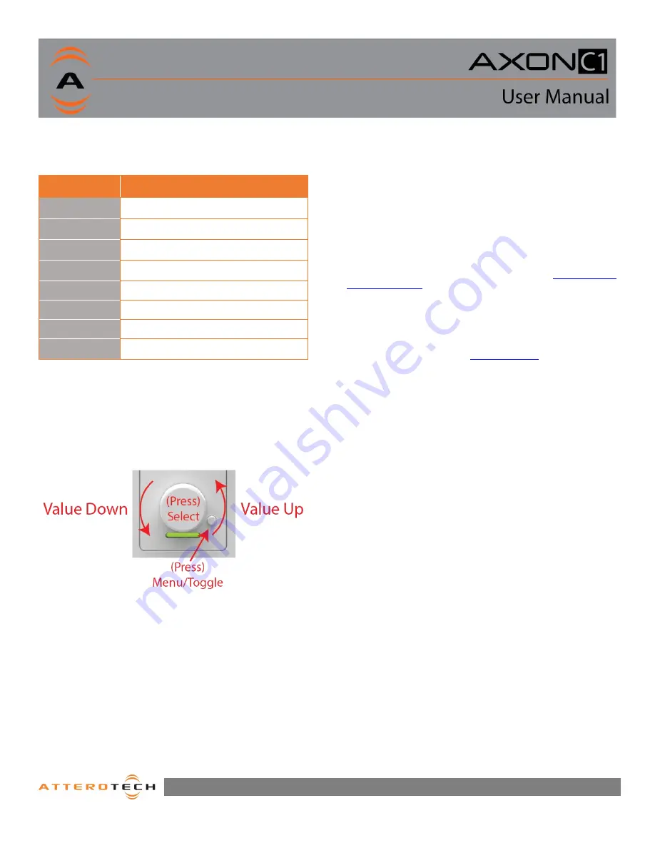
2.3 – Controls 

Once configured, the C1 controls the desired devices simply 
using the encoder knob and menu/toggle button. 


3

 – Device Configuration and 

Workflow Overview 

The C1 may be programmed to interface with many 3

rd

  party 

products supporting networked control over UDP or TCP/IP based 
protocols. 
 
Integrators will first use unIFY Control Panel to create the basic 
menu structure required for the end user application 
requirements.  Then depending on the target system or products 
to be controlled, the integrator will configure the underlying 
control mappings. 
 
For a complete description of the C1 menu customization 
features found in unIFY Control Panel, consult the 

online software 

support resources

 on the Attero Tech support desk 

 
In addition, Attero Tech C1 Integration  Guides and supporting 
integration materials are also located on the online support desk 
to expedite the integration of C1 controllers with common AV 
systems such QSC Q-SYS based DSP systems. 
 
Refer to the support desk and 

C1 product page

 on the Attero Tech 

website for the latest links to integration support resources. 


3.1– IP Address Setup 

*************************  IMPORTANT  ************************** 

Failure to correctly configure IP addresses will not allow a  C1 
device to correctly authenticate in the unIFY Control Panel 
software, and configuration and control to and from the C1 will 
not be possible. 

******************************************************************* 

 
In order to configure a C1  or  to update  C1  firmware, a  PC will 
need to be able to communicate with it over the network. While 
all  C1  devices will be discovered regardless of the IP address 
setup on the PC (the C1 utilizes mDNS for device discovery), full 
communication can only occur if the PC and the device have 
compatible IP addresses. 
 
By default, C1 is set to get a dynamic IP address. If the C1 device 
does not find a DHCP server to retrieve an IP address from, it will 
give itself an automatic private IP address (APIPA) instead. An 
APIPA is always in the range 169.254.x.y. 
 
To ensure communication, the PC can either be set to get a 
dynamic IP address, or be given a static IP address in the range 
169.254.x.y. The PC may require a restart for the changes to take 
effect. 
 

Summary of Contents for C1

Page 1: ...614 00050 Rev 00_a Attero Tech LLC 2019 11 19 18 Programmable IP Remote ...

Page 2: ...ovided plug does not fit into your outlet consult an electrician for replacement of the obsolete outlet 10 Protect the power cord from being walked on or pinched particularly at plugs convenience receptacles and the point where they exit from the apparatus 11 Only use attachments accessories specified by Attero Tech 12 Use only with the cart stand tripod bracket or table specified by the manufactu...

Page 3: ...breach of warranty as outlined above NEITHER ATTERO TECH LLC NOR ANYONE INVOLVED IN THE PRODUCTION OR DELIVERY OF THE EQUIPMENT SHALL BE LIABLE FOR ANY INDIRECT SPECIAL PUNITIVE CONSEQUENTIAL OR INCIDENTAL DAMAGES ARISING OUT OF THE USE OR INABILITY TO USE THIS EQUIPMENT EVEN IF ATTERO TECH LLC HAS BEEN ADVISED OF THE POSSIBILITY OF SUCH DAMAGES IN NO EVENT SHALL THE LIABILITY OF ATTERO TECH LLC E...

Page 4: ...iew 1 1 1 What s in the Box 1 2 Device Installation 1 2 1 Mounting 2 2 2 Display and LED Status Indications 3 2 3 Controls 3 3 Device Configuration and Workflow Overview 3 3 1 IP Address Setup 3 3 2 Factory Reset 4 3 3 Firmware Updates 4 ARCHITECTS ENGINEERS SPECIFICATION i Device Specifications ii ...

Page 5: ...using the C1 controller In addition a Q SYS Designer plug in is readily available that minimizes the need for any custom programming 1 1 What s in the Box The C1 comes supplied with the following o Axon C1 device P N 900 00223 01 o Includes interchangeable white and black Decora style inserts o 1 White US Single Gang Decora cover plate o 1 Black US Single Gang Decora cover plate 2 Device Installat...

Page 6: ...already running and PoE is enabled the unit will power up and the green status LED on the front of the device will turn on With the cable attached carefully place the C1 into the wall box taking care to not trap the cabling Once in place secure it with the screws provided Once the unit is secured in the wall box fit the Decora plate and secure it with the screws provided The C1 comes in a single g...

Page 7: ...ption of the C1 menu customization features found in unIFY Control Panel consult the online software support resources on the Attero Tech support desk In addition Attero Tech C1 Integration Guides and supporting integration materials are also located on the online support desk to expedite the integration of C1 controllers with common AV systems such QSC Q SYS based DSP systems Refer to the support...

Page 8: ...vice setting the PC s IP address to also obtain a dynamic IP address should then allow the PC to communicate fully with that device Figure 4 Reset button access The factory reset is performed on the front panel of the unit The function is activated by pressing and holding the encoder button and the menu toggle button simultaneously for 5 seconds The unit will initialize and all user settings inclu...

Page 9: ...ang US wall box The unit shall accept either IEEE 802 3af standard PoE from an IEEE 802 3af PoE compliant network switch or mid span injector The unit shall support a flexible programming interface for targeting control of 3rd party AV systems and products The unit shall include a software plugin for simple interfacing with QSC Q SYS based DSP systems The network control interface shall be complia...

Page 10: ...umption 2W Max Physical Dimensions Width 1 74 Height 4 2 Depth 1 77 1 19 in wall Weight 0 25 lbs Regulatory Compliance Certifications FCC Part 15 Subpart B Class A EMC CE EN55032 EMC EN55035 ESD WEEE RoHS REACH Environmental Operating Specifications Operating Temperature 0 to 40 C Controls User Interface One rotary pushbutton encoder knob One pushbutton toggle selector Display Display Type 1 5 Dia...

Reviews: