16
W H I T E
A X M I N S T E R
W
Parts Identification and Description (Continued)...
On/Off switch
(See Fig 9a/b)
A NVR switch panel mounted on the left front
of the machine. Green ‘I’ will start the
machine; red ‘O’ to stop. Should power be
interrupted whilst the machine is in use, the
NVR will ensure the machine has not remained
in the switched on condition when power is
restored. The top cover of the switch
provides a security lock, in that when it is
closed a small padlock can be snapped into
place to prevent the machine being run. It also
acts as a quick action ‘emergency off’ switch,
in that an interior moulding inside the cover
depresses the Off switch when it is closed.
Being hinged on one side the cover can be
‘slapped’ shut to switch the machine off
quickly.
Tool Guard
(See Fig 9)
A clear moulded plastic shield mounted on a
swing arm. The pivot of the swing arm is a
metal rod that is fitted through a lug located at
the left rear of the milling head. On the top of
the rod is a riser cam, that activates an
interlock microswitch, so that the machine will
not run unless the guard is in place. The
position of the guard and the riser cam can be
altered to allow the guard to be postioned
around the tool anywhere within the work
envelope of the machine.
Quill clamp
(See Fig 9)
A bent chrome rod lever, inserted into a
threaded hole that is machined in the side of
the main bore housing the spindle sleeve.
Screwing the lever in will drive the end of the
rod forward against a contact pad which will
clamp the quill thus locking it in position.
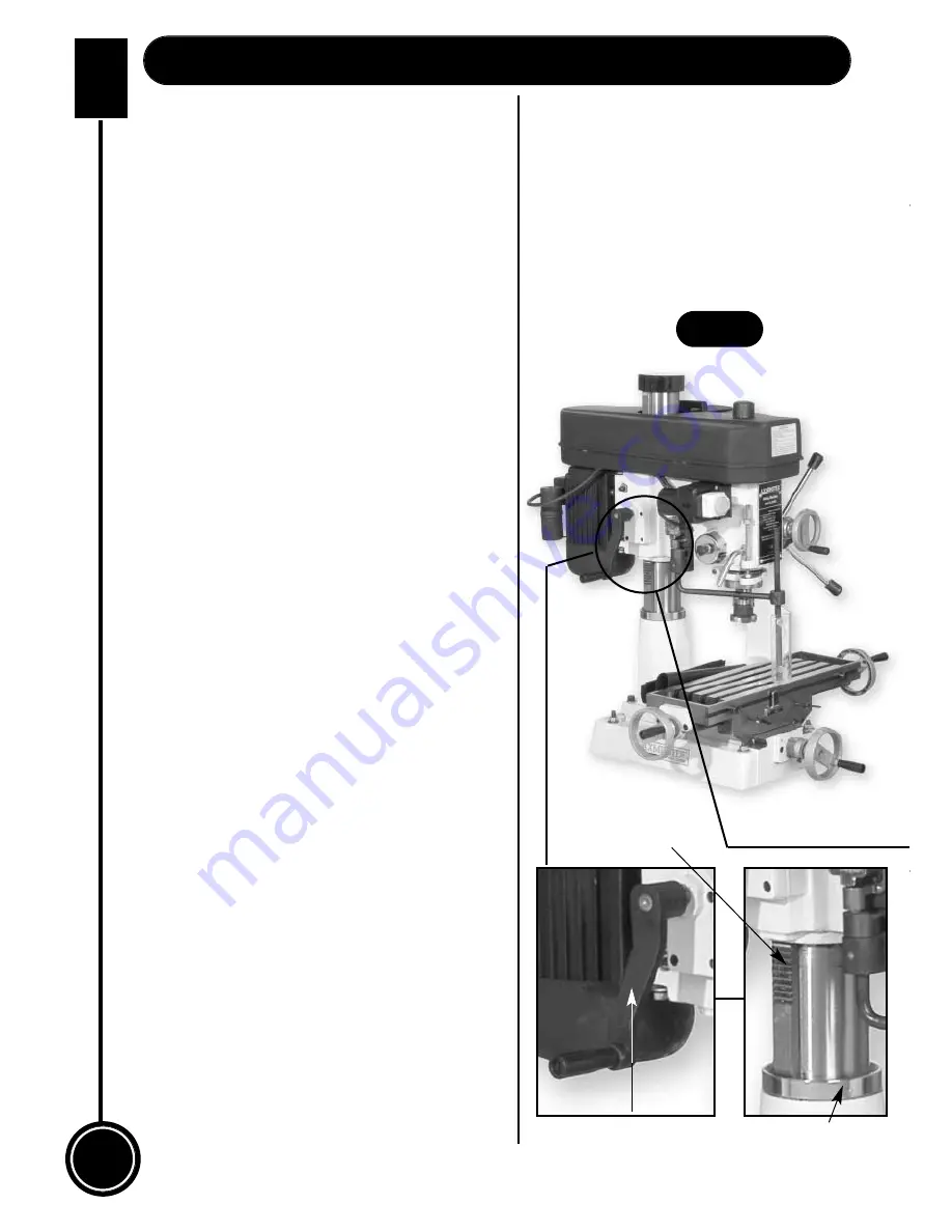
Rise and fall mechanism
(See Fig 8)
The rise and fall mechanism is a rack and
pinion device, which drives the head up and
down the main tool post. The rack is mounted
on the main tool post, housed in two bevelled
cup keepers (one at the top, one at the
bottom) which allows the rack to pivot around
the tool post with the milling head. The pinion
gear is housed to the left rear of the head
casting. The pinion gear is driven by a short
shaft onto which the bent crank handle
is fitted. NOTE. The rise and fall
mechanism should not be operated
unless the head clamping bolts and
nuts have been loosened off.
Rise & fall
handle
Bevel housing
Rise & fall
rack
Fig 8
Summary of Contents for ZX25M
Page 22: ...22 W H I T E AXMINSTER W Mill Drill Oiling Points Continued www axminster co uk Oil OIL ...
Page 24: ...24 W H I T E AXMINSTER W Parts Breakdown ...
Page 25: ...W H I T E AXMINSTER W 25 Parts Breakdown FREEPHONE 0800 371822 ...
Page 26: ...26 W H I T E AXMINSTER W www axminster co uk Parts LIst ...
Page 27: ...W H I T E AXMINSTER W 27 Parts List FREEPHONE 0800 371822 ...


