


Assembly
8
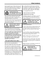
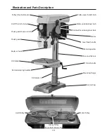
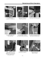
Please read through the section entitled
illustration and parts description, to
identify the parts quickly and easily.
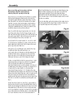
Place the base (2) on the bench or (floor) and place
the mounting flange of the column (5) onto the
seating flange of the base, align the holes. Use the
four Hex bolts (12) secure the column to the base
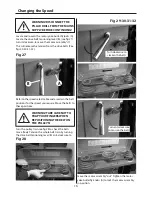
(see fig 1). Loosen the socket grub screw holding
the cup chamfered retaining collar to the column
(with the supplied Hex key), remove it and the rise
and fall rack, put safely aside (see fig 2).
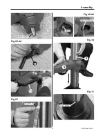
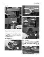
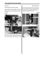
Take the drill table mounting bracket arm (3) and
twist the worm drive shaft with your fingers such
that the whole shaft protrudes from the casting and
the worm gear itself is clear of the square recess in
the main body of the casting (see fig 3-4).
Locate and fit the crank handle (13-14) to the shaft,
ensuring that you tighten the grub screw onto the
machined flat on the shaft. This will keep the worm
gear in position (see figs 5-6).
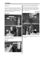
Pick up the rise and fall gear rack, identify the top
and the bottom, (the rack gearing is cut
asymmetrically, with the gear cut extending closer
to the bottom), make sure you have the rack the
right way up, as it will allow you to drive the drill
table up and down over its full range (see fig 7).
Fit the rise and fall rack into the square recess in the
mounting body casting, ensure that it is engaged
with the pinion, (see figs 8-9) and lower the
combined mechanism over the column (5). Allow it
to slide down the column until the rise and fall rack
is located in the cup chamfer in the top of the
mounting flange (see figs 10-11). Replace the cup
chamfered retaining collar over the column and slide
it down onto the top of the rack. Lock it in place with
the grub screw, ensuring that it has captured the
upper end of the rack securely, but not too tight that
the rack can not be swivelled around the pillar (see
fig 2).
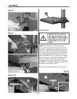
Check that the bracket can be driven up and down
the column and can swivel around the pillar. Locate
the Bristol clamping handle (8) and screw it into the
threaded hole to the rear of the mounting bracket
arm (3) and tighten, (see fig 12) check it has ‘pinched’
up on the column and the bracket is immobile; both
in it’s up and down travel and swivel movement.
Fig 01
Fig 02
Fig 03-04
Slot the drill table (4a) into the machined hole to the
front of the mounting arm (3a) and screw a Bristol
clamping handle (8) into to the threaded hole
beneath the table and tighten, (see fig 13) check it
has ‘pinched’ up on the drill table spigot and the drill
table is immobile.
For 505206 offer up the face plate of the table (4b) to
the face plate of the mounting arm (3b) and secure
using the large Hex bolt, see figs 14-15.
Mounting flange
Hex Bolts
2
5
Retaining collar
Grub screw
Worm drive shaft
3
Summary of Contents for Trade AT2001DP
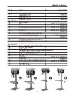
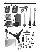
Page 4: ...What s Included 4 2 3 1 a a a a b b b c b 4 6 7 8 9 10 11 12 13 15 16 14 5 ...
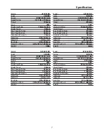
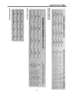
Page 17: ...Speed Select Table 17 505204 AT2801DP 505203 AT2001DP 505205 AT2801FDP 505206 AT3202FDP ...
Page 21: ...Parts Breakdown List 505203 21 Continues Over ...
Page 24: ...Parts Breakdown List 505204 505205 24 ...
Page 27: ...Parts Breakdown List 505206 27 Continues Over ...
Page 30: ...Wiring Diagram 505203 505204 505205 30 ...
Page 31: ...Wiring Diagram 505206 31 ...