
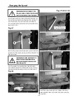


Changing the Speed
16
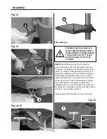
WARNING! DISCONNECT THE
PILLAR DRILL FROM THE MAINS
SUPPLY BEFORE CONTINUING!
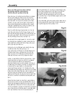
Locate and loosen the motor yoke butterfly locks (A).
Locate the drive belt tensioning lever (B), (see fig 27)
turn it clockwise, to move the motor assembly “in”.
This will release the tension from the drive belts (See
figs 29-30-31-32).
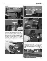
Fig 27
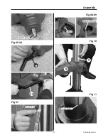
Turn the pulley train,see fig 28 to check the belts
move freely. Tension the whole belt train by turning
the drive belt tensioning lever (B) anti-clockwise, to
WARNING! TAKE CARE NOT TO
TRAP YOUR FINGERS WHEN
REPOSITIONING THE BELT ON
THE PULLEYS!
Refer to the speed select table and ascertain the belt
positions for the speed you require. Move the belts to
these positions.
Fig 28
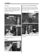
Fig 29-30-31-32
Turn anti-clockwise
to tension the belts
Turn clockwise to
slacken the belts
move the motor assembly “out”. Tighten the motor
yoke butterfly knobs (A) to lock the motor assembly
in position.
A
B
Summary of Contents for Trade AT2001DP
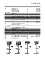
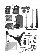
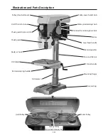
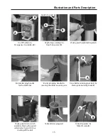
Page 4: ...What s Included 4 2 3 1 a a a a b b b c b 4 6 7 8 9 10 11 12 13 15 16 14 5 ...
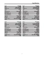
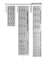
Page 17: ...Speed Select Table 17 505204 AT2801DP 505203 AT2001DP 505205 AT2801FDP 505206 AT3202FDP ...
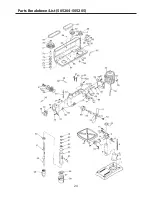
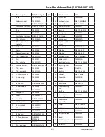
Page 21: ...Parts Breakdown List 505203 21 Continues Over ...
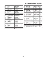
Page 24: ...Parts Breakdown List 505204 505205 24 ...
Page 27: ...Parts Breakdown List 505206 27 Continues Over ...
Page 30: ...Wiring Diagram 505203 505204 505205 30 ...
Page 31: ...Wiring Diagram 505206 31 ...