


Setting Up the Saw
23
Fig 63
Pointer
Adjusting screw
Scale
Setting the Fence
To make sure the guide fence is at 90˚ to the table, line
up the guide fence with the edge of the table’s ‘T’ slot, see
fig 64. If you find that the fence is out of alignment follow
the steps below:
1 Clamp down the fence by pushing the locking
lever down, see fig 65.
2 Loosen the 4 Hex bolts that secures the fence and
adjust until the fence is in alignment with the ‘T’ slot in
the table, then re-tighten the bolts, see fig 66.
3 Replace the fence assembly to its original position.
Fig 64
Fig 65-66
‘T’ slot
Fence
Hex bolts
Setting the Blade Guides (above table)
DISCONNECT THE SAW FROM
THE MAINS SUPPLY!
Lower the upper blade guide to approximately 1
1/2”(38mm) above the table. Clamp in place. Loosen
the butterfly screw (A), holding the guide assembly in
place and adjust the fore and aft position by turning the
adjustment knob (B) so that the leading edges of the
side guide bearings are approximately 2 mm behind the
gullets of the saw blade. Re-tighten the butterfly screw,
see fig 67-68. Loosen the butterfly screw (C) that clamps
the rear thrust bearing in position and turning the
adjustment knob (D) until the thrust bearing is
approximately 2mm behind the blade, re-tighten the
butterfly screw, see fig 69-70-71.
Fig 67-68
A
B
Fig 69
Continues Over....
C
Summary of Contents for SBW-350
Page 1: ...SBW3501B Bandsaw Code 501199 AT M 09 01 2018 REF 508308 ...
Page 4: ...4 5 6 7 What s Included 4 2 2 3 ...
Page 5: ...What s Included 5 10 9 8 15 14 13 12 11 16 17 18 19 20 21 22 23 24 25 26 ...
Page 29: ...Parts Breakdown List 29 Continues Over Main Saw Assembly ...
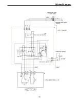
Page 35: ...Wiring Diagram 35 ...