background image

11

Common trouble problems and their Solutions

Symptom

Possible Cause

Possible Solution

Motor can not

start

1. The power supply is not on.

2. Low voltage.

3. Motor open circuit or loose

connection.

4. The external input socket is

broken.

5. May which switch is bad or

connect line loosen;

1. Turn on the emergency stop button

2. Check that the voltage of the power

supply is correct.

3. Check that all the connections of the

motor are loosened or disconnected.

4. Check and confirm the input socket is

ok.

5. Check switch and the connect lines is

tighten.

Fuse or circuit

breaker

disconnected

1. Wire or plug short circuit

2. Circuit board short circuit

3. Power supply fuse or circuit

breaker incorrect.

1. Check wires and plugs for damaged or

missing insulation and replace them with

extension wires.

2. Check the voltage of the power supply

is correct

3. Check that all connections of the motor

are loose or welded or insulated, and

replace the correct fuse or circuit breaker

in time

Motor

overheating

1. Motor overload

2. Air circulation of motor is

restricted

1. Reduce the load of motor

2. Clean the motor and ensure smooth

circulation of air

The hand wheel

of a transverse

or feed trawl is

too loose

1. The adjusting screw is not in

place.

2. Hand wheel loosened

3. Wire rod assembly old or not

in place

1. Tighten the adjusting screw and

lubricate the bed

2. Tighten the hand wheel knob

3. Tighten all loose knobs on the thread

rod assembly.

The machine

makes constant

noise

1. The gear or bearing is out of

order.

2. The motor is out of order.

1. Replace damaged gear or bearing

2. Replace motor

During

operation, the

machine stops

1. Drilling and milling too deep

2. The wrong speed or feed

speed was used in the drilling

and milling operation.

3. Milling cutter damage

4. Motor damaged

5. Gear damaged

1. Reduce drilling depth

2. Choose the right speed

3. Replacement milling cutter

4. Replacement motor

5. Replacement gear

Finish surface

difference

1. Speed or feed speed error

2. Milling cutter broken or

wrong selected

1. Change the milling cutter by adjusting

the correct speed or feed speed

2. Change the cutter

Difficult to move

the end part on

the guide rail

1. Drying of guideway

2. Z shaft hand wheel to tighten

3. Over compacted with debris

on guide rail

1. Lubricating oil

2. Adjusting screw

3. Cleaning guide

T - type nut is

difficult to fix

1. T type nut defect or damaged

2. T-groove on the wrong

working table

1. Replacement of type T nut

2. Replacement of table or well-used T

slot

Summary of Contents for 107154

Page 1: ...SX2 7 Mill Drill Code 107154 Original Instructions AT M 07 07 2020 BOOK VERSION 2 ...

Page 2: ... been issued by Shangjai SIEG Machinery CO Ltd at No 555 Caoan Rd SHANGHAI CHINA and complies with the relevant essential health and safety requirements 2006 42 EC 2014 30 EU EN 55014 1 2017 EN 55014 2 2015 declares that the machinery described This machine complies with the following directives EU Declaration of Conformity EN 61000 3 2 2014 EN 61000 3 3 2013 Signed Andrew Parkhouse Operations Dir...

Page 3: ...ing or jewelry as they can be caught in moving parts 9 Wear restrictive hair covering to contain long hair 10 Use eye and ear protection Always wear 11 Keep proper footing and balance at all times 12 Do not reach over or across running machines Before operations 1 Be sure the switch is OFF when not in use and before plugging in 2 Do not attempt to use inappropriate attachments in an attempt to exc...

Page 4: ...m End mill capacity 16 mm Face mill capacity 50 mm Throat 190 mm Max distance spindle to table 370 mm Spindle taper Choice of MT 3 or R8 Spindle speed 100 2000 rpm 10 Table effective size 700x160 mm T slot size 12 mm Table longitudinal travel X 400 mm Cross travel Y 190 mm Headstock travel Z 290 mm Power 750 W Overall dimension L W H 825 620 880 mm Packing size L W H 960 760 1060 mm Weight Net Gro...

Page 5: ...3 axis display use three axis magnetic grating ruler Digital readout display Model SX2 7 picture Model SX2 7D picture The main features and advantages of this product 1 The highest speed arrange 2000 rpm variable spindle speed 2 Spindle speed digital readout 3 Tapping function 4 Brush less DC motor 5 Chuck guard with safety switch optional 6 Feeding depth digital readout 7 Fine feeding 8 With two ...

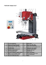
Page 6: ...ock the spindle sleeve 9 On Off button 10 Emergency stop switch 11 Variable speed control knob 12 Spindle speed display 13 Tapping choose button 14 Spindle box cover 15 Fine feeding handle 16 Spindle box 17 Control handle with tapping button 18 Z axis handwheel 19 Back cover PC Board inside 20 Fine feeding locking knob 21 Power socket with fuse box 22 X axis handwheel 23 Locking handle assembly 24...

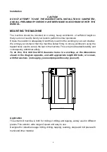
Page 7: ...ed firmly to strong workbench using the tapped holes used to secure the feet to the machine This is to provide added stability and consequently additional safety To do this first drill four M12 clearance holes in a worktop at the dimensions shown in the diagram opposite and with appropriate length M8 bolts or screws with flat washers not supply you need prepare these by yourself Application This s...

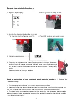
Page 8: ...tion Under tapping circumstances have forward and reverse direction Press the tapping function lock button E then is button will bright then you can press a green button to choose the spindle run to forward or reverse The green button total 3 pcs they on the right of the spindle box in the lifting lever You can see the word of forward or reverse on the right of the display D it easy to show the us...

Page 9: ...ndle all can control so it is very easy to do See the picture on the right position Brief introduction of conventional mechanical operation Picture for reference only 1 The clamping tool and work piece must stop the machine first 2 Clean the inner hole of the spindle and the conical surface of the tool rod push the tool rod into the inner hole of the spindle and put in the pull rod to hang the too...

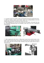
Page 10: ...ling parts we must lock the spindle box and spindle at the same time lock the longitudinal transverse plug iron according to the need so as not to change the machining size 7 When replacing the drill chuck or milling chuck open the top shield loosely on the edge loosen the screw thread of the pull rod 2 3 teeth then use a hammer to knock the taper handle away from the main shaft and finally loosen...

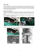
Page 11: ...ffecting the use and beauty of the machine Machine tool lubrication In order to ensure the long service life of the machine and the effective operation of the machine tool lubricating oil or lubricating oil is regularly added to each moving joint and joint Where lubricating oil is needed is mainly the dovetail surface in three directions of XYZ axis Position as indicated by arrow The main ones tha...

Page 12: ... The hand wheel of a transverse or feed trawl is too loose 1 The adjusting screw is not in place 2 Hand wheel loosened 3 Wire rod assembly old or not in place 1 Tighten the adjusting screw and lubricate the bed 2 Tighten the hand wheel knob 3 Tighten all loose knobs on the thread rod assembly The machine makes constant noise 1 The gear or bearing is out of order 2 The motor is out of order 1 Repla...

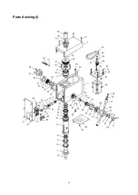
Page 13: ...12 Parts drawing I ...

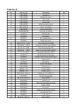
Page 14: ...7 Deep groove ball bearing 80107 1 I 13 7_70 12 x 22 x 5 Thrust ball bearing 12 22 5 2 I 14 LX3C0219 Spindle below oil seal ring I 1 I 15 LX3C0216 Spindle sleeve below oil seal ring II 1 I 16 LX3C0210 Up washer II 1 I 17 LX3C0209 Up washer 1 I 18 LXN3A0226 Sleeve limit washer 1 I 19 LXN3A02B08 Bearing seat 1 I 20 GB 893 1 62 Check ring 62 1 I 21 GB 894 1 35 Check ring 35 1 I 22 GB 810 88 M27x1 5 S...

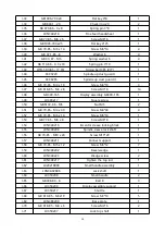
Page 15: ...300 165 1 I 49 LX3C0217 Square screw 1 I 50 GB 6172 86 M5 Nut M5 2 I 51 GB 70 85 M4 x 40 Screw M4 40 4 I 52 GB 79 85 M6 x 14 Screw M6 14 1 I 53 GB 77 85 M6 x 8 Screw M6 8 1 I 54 LXN3A0216 Eccentric sleeve locking block 1 I 55 LXN3A0208 Spindle sleeve lock shaft 1 I 56 GB 70 85 M10 x 20 Screw M10 20 1 I 57 LXN3A0211 Connect support 1 I 58 GB 70 85 M5 x 12 Screw M5 12 7 I 59 LXN3A0202 Bevel wedge 1 ...

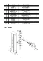
Page 16: ...8 85 M3 x 4 Screw M3 4 1 I 77 LXN3B020700 Control handle assembly 3 I 78 LXN3B020800 F R control pole assembly 3 I 79 GB2089 80 0 8x6x25 Compress spring 0 8 6 25 3 I 80 GB 896 86 3 Spring washer 3 3 I 81 LXN3B0203 Motor support plate 1 I 82 LXN3B0201 Motor timing pulley 1 I 83 LXN3B0205 Washer 1 I 84 GB 819 85 M5x20 Screw M5 20 1 I 85 LX3C02A03 Key use for R8 spindle 1 Parts drawing 2 ...

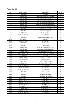
Page 17: ...A Metric rise and down scale dial 1 LXN3A0909B Inch rise and down scale dial 2 15 GB 879 86 3 x 20 Spring round pin 3 20 1 2 16 GB T 276 94 6001 Deep groove ball bearing 6001 4 2 17 GB 65 85x55 Screws 8 55 1 2 18 GB 889 86 M8 Hex locking nut M8 1 2 19 GB1096 79 4x16 Parallet key 4 16 1 2 20 LXN3A0902 Rise and down shaft 1 2 21 GB 879 86 3 x 16 Spring round pin 3 16 1 2 22 GB 70 85 M5 x 30 Screw M5...

Page 18: ...A04 Metric cross leadscrew 1 LXN3A11A04A Inch cross leadscrew 3 6 LXN3A1106 Left end cover 1 3 7 LXN3A1107A Metric cross leadscrew nut 1 LXN3A1107B Inch cross leadscrew nut 3 8 LXN3A1111 Longitudinal bevel wedge 1 3 9 LXN3A1113A Metric longitudinal leadscrew nut 1 LXN3A1113B Inch longitudinal leadscrew nut 3 10 LXN3A11A05 Cross bevel wedge 1 3 11 GB 301 84 8101 Thrust ball bearing 8101 4 ...

Page 19: ... LXN3A11A06 Scale ruler 1 LXN3A11A06A Inch scale ruler 3 28 GB 70 85 M6 x 16 Screw M6 16 6 3 29 GB 119 86 A 4 x 20 Round pin 4 20 6 3 30 LC5C0315 0 position label 1 3 31 LX2021800 Small handle assembly 2 3 32 LXN3A0223 Wedge screw 4 3 33 LXN3A0217 Lock top bar 1 3 34 LXN3A1109 Longitudinal wedge lock top bar 1 3 35 GB 70 85 M4 x 14 Screw M4 14 4 3 36 GB 70 85 M5 x 20 Screw M5 20 4 3 37 GB 117 86 A...

Page 20: ...4 Washer 2 3A 2 LX21001A00 X axis magnetic ruler assembly 1 3A 3 GB 818 85 M3 x 10 Screw M3 10 2 3A 4 LX3 51001 X axis magnetic ruler 1 3A 5 LXN3A10B01 Reader support 2 3A 6 GB 70 85 M4 x 10 Screw M4 10 4 3A 7 LXN3A10A01 X axis magnetic ruler 1 3A 8 GB 70 85 M4 x 25 Screw M4 25 2 3A 9 MG10V DRO with readers assembly 3 3A 10 GB 818 85 M3 x 12 Screw M3 12 6 3A 11 LX21005 Reader block 1 3A 12 LXN3A10...

Page 21: ... relative mode clear key Long press 4s sensor adaptive calibration mode Function status short press modify the current display parameters normal short press relative absolute mode switching Long press 4s change the sensor increment direction Function status short press switch key parameter shift Long press 4s enter the menu Short press modify confirmation button Short press X Y Z select button Ele...

Page 22: ...nfirm P03 P33 P63 Measuring direction or via shortcut 0 1 1 0 or 1 represents two directions Change the direction of the sensor and also change the direction of measurement P04 P34 P64 Length resolution 0 1 2 3 4 4 0 INCH 1 1 2 0 1 3 0 05 4 0 01 After modification press Enter to confirm P06 P36 P66 Scale factor 0 00001 2 99999 1 Display value measure true value scale factor After modification pres...

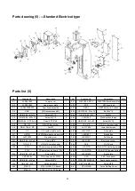
Page 23: ... 1 4 19 LX20002 Strip 1 4 6 GB 97 1 85 6 Washer 6 1 4 20 LX20004 Strip 1 4 7 LX3C23C0401 Inner protect guard 1 4 21 LXN3A2303 Block 1 4 8 LX3C23C03 Outside protect guard 1 4 22 GB 818 85 M5 x 6 Screw M5 6 6 4 9 GB 835 88 M5x20 Knurled screw M5 20 2 4 23 LX20003 Dust guard 1 4 10 GB 97 1 85 5 Washer 5 2 4 24 LXN3A2302 Guideway protect cover 1 4 11 GB 889 86 M6 Lock nut 1 4 25 LXN3A2305 Finder block...

Page 24: ... 2 5 29 LX3C1806 Lower dust screen 1 5 10 Y 2 Y 2 Liquid crystal board 1 5 30 LX3C23C01 Shoe plate 1 5 11 HY57B HY57B Emergency stop switch 1 5 31 LX351801 Electric Box 1 5 12 LX3C1802 Grounding row 1 5 32 LSX352511 Switch sign 1 5 13 GB 818 85 M4 x 8 Screw M4 8 14 5 33 LSX351801 Electric box cover 1 5 14 HTS 410 HTS 410 Lsolation pillar 8 5 34 GX 2 GX 2 Knob 1 5 15 ZD 2 DC power supply board 230V...

Page 25: ...6 M3 Nut M3 2 5A 32 LX3C1806 Lower dust screen 1 5A 11 Y 2 Y 2 Liquid crystal board 1 5A 33 LX351813A Wire clip holder 1 5A 12 HY57B Emergency stop switch 1 5A 34 LXN3A18B02 Wire clip holder 1 5A 13 LX3C1802 Ground row 1 5A 35 LX3C23C01 Shop plate 1 5A 14 GB 818 85 M4 x 8 Screw M4 8 18 5A 36 LX351801 Electric box 1 5A 15 HTS 410 HTS 410 Lsolation pillar 8 5A 37 LSX352511 Swicth sign 1 5A 16 ZD 2 2...

Page 26: ...ZD 2 DC power supply plate FU Fuse 8A 230V 15A 110V X 4D Knob panel SB2 Tapping button Z Filter only use on 230V XC Socket with fuse SB1 Emergency stop switch Y 2 Liquid crystal board SQ Micro switch SB3 Start stop button L1 Magnet ring only on 230V L2 Magnet ring SB4 Tapping button ...

Page 27: ... power supply plate FU Fuse 8A 230V 15A 110V X 4D Knob panel SB2 Tapping button Z Filter only use on 230V XC Socket with fuse SB1 Emergency stop switch Y 2 Liquid crystal board SQ Micro switch SB3 Start stop button L1 Magnet ring only on 230V L2 Magnet ring MG10V Display SB4 Tapping button ...

Page 28: ...3C004 1 pce 7 Oil cup 1 pce 8 T nut X22001 2 pcs 9 L hex wrench assembly X3C2003 1 件 Below parts usually fixed on the machine According to choice of MT3 or R8 10 B16 drill chuck J2113 1 13mm B16 1 pce MT3 type 11 MT3 taper shank X20206 1 pce 12 locking bolt assembly X3C021100 X3C021101 1 pce 13 slanting wedge X3C2002 1 pce 14 JT6 drill chuck 3 16mm JT6 1 pce R8 type 15 R8 taper shank X302A04 A 1 p...

Page 29: ...ed and recycled separately EU Countries Only The Axminster guarantee is available on Craft Trade Engineer Air Tools CNC Technology Series machines Buy with confidence from Axminster So sure are we of the quality we cover all parts and labour free of charge for three years For more information visit axminstertools com 3years Axminster Tools Axminster Devon EX13 5PH axminstertools com ...

Reviews: