Assembly
7
C
150mm Tool rest
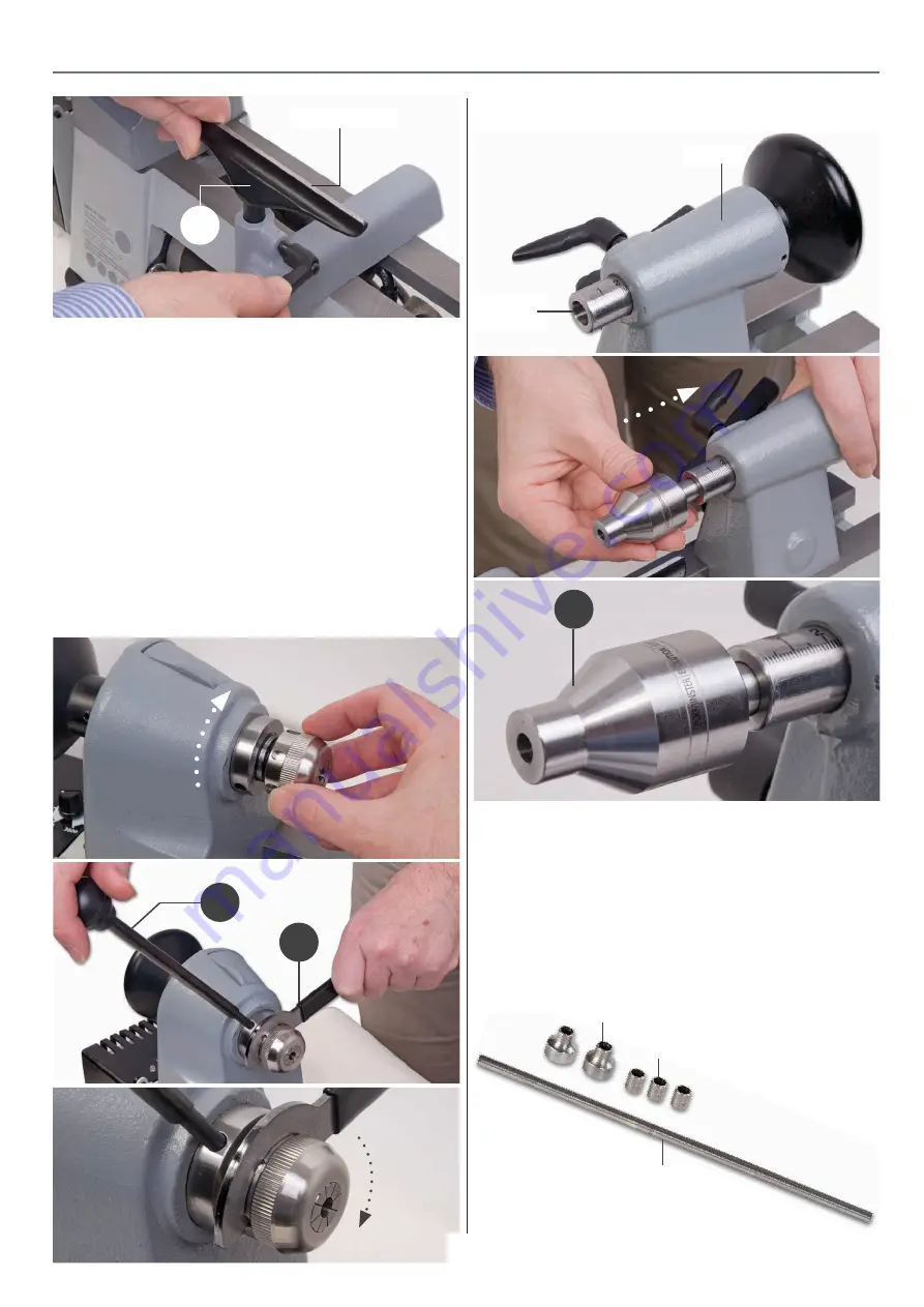
5. Locate the collet chuck (F), Evolution hollow revolving centre
(G), Pen mandrel assembly (H), ‘C’ spanner (I) and push rod (B).
6. Put to hand the ER20 collet chuck nut with the 6-5mm collet
(F) attached. Screw the collet chuck assembly on to the spindle
taper on the head stock, see fig 08.
7. Locate the ‘C’ Spanner (I) and push rod (B). Insert the push
rod into the pre-drilled hole in the spindle collar, introduce the
‘C’ spanner (I) over the collet check (F) until the locating pin
engages into one of the elongated holes around the collet
chuck (F). While holding the push rod in place, tighten the
collet chuck, see fig 09-10.
Fig 08-09-10
B
I
Fig 12-13-14
8. Locate the evolution revolving live centre (G), insert the
taped end into the barrel shaft on the tailstock until it locks in
place, see fig 12-13-14.
Tailstock
barrel
G
Tailstock
Pen Mandrel
1. Locate the pen mandrel assembly (H), remove the bushings
and mandrel spacers, see fig 15.
Fig 15
Bushings
Mandrel shaft
Mandrel spacers
Continues Over....
Summary of Contents for AT150PPL
Page 18: ...Exploded Diagrams Parts Lists 18 ...
Page 20: ...Wiring Diagram 20 ...
Page 21: ...Notes 21 ...
Page 22: ...Notes 22 ...
Page 23: ...Notes 23 ...


