


Setup & Adjustment
8
6
2
10
8
7
4
5
3
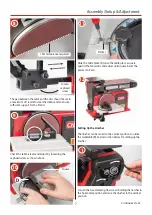
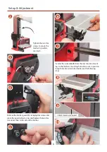
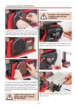
Tighten the two Hex
screws to secure the
linisher in position,
see step 3.
Remove the linisher guard (E) clamping Hex screws and
place the guard safely to one side. Replace the two Hex
screws/washers to the side of the linisher.
Transfer the work table (B) from the disc function mount-
ing to the linisher’s mounting hole and secure in position.
Setup the table as described earlier, see the following
steps.
1.6mm clearance required
9