


Machine Vision MIRU130 Board
AMI BIOS Setup Utility
45
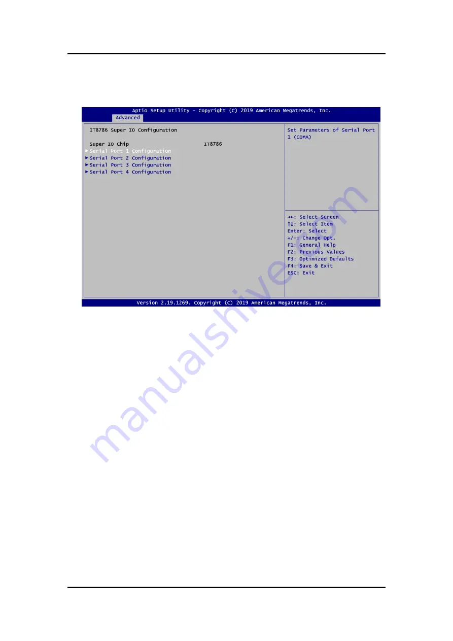
IT8786 Super IO Configuration
You can use this screen to select options for serial port configuration, and change the
value of the selected option. A description of the selected item appears on the right side of
the screen. For items marked with
“
”, please press <Enter> for more options.
Serial Port 1~4 Configuration
Use these items to set parameters related to serial port 1~4.
Summary of Contents for MIRU130
Page 1: ...MIRU130 Machine Vision SBC with AMD RYZENTM Embedded V1605B V1807B User s Manual ...
Page 6: ...vi This page is intentionally left blank ...
Page 10: ...Machine Vision MIRU130 Board 4 Introduction This page is intentionally left blank ...
Page 12: ...Machine Vision MIRU130 Board 6 Board and Pin Assignments Bottom View Side View ...
Page 13: ...Machine Vision MIRU130 Board Board and Pin Assignments 7 2 2 Board Layout Top View ...
Page 14: ...Machine Vision MIRU130 Board 8 Board and Pin Assignments Bottom View ...
Page 34: ...Machine Vision MIRU130 Board 28 I O Connection 5V Voltage Type ...
Page 38: ...Machine Vision MIRU130 Board 32 Operating This page is intentionally left blank ...
Page 40: ...Machine Vision MIRU130 Board 34 Hardware Description 5 4 I O Port Address Map ...
Page 42: ...Machine Vision MIRU130 Board 36 Hardware Description ...
Page 43: ...Machine Vision MIRU130 Board Hardware Description 37 ...
Page 44: ...Machine Vision MIRU130 Board 38 Hardware Description ...
Page 45: ...Machine Vision MIRU130 Board Hardware Description 39 ...
Page 61: ...Machine Vision MIRU130 Board AMI BIOS Setup Utility 55 Console Redirection Settings ...


