


IFO2225-873 Series User’s Manual
AMI BIOS Setup Utility
47
3.7
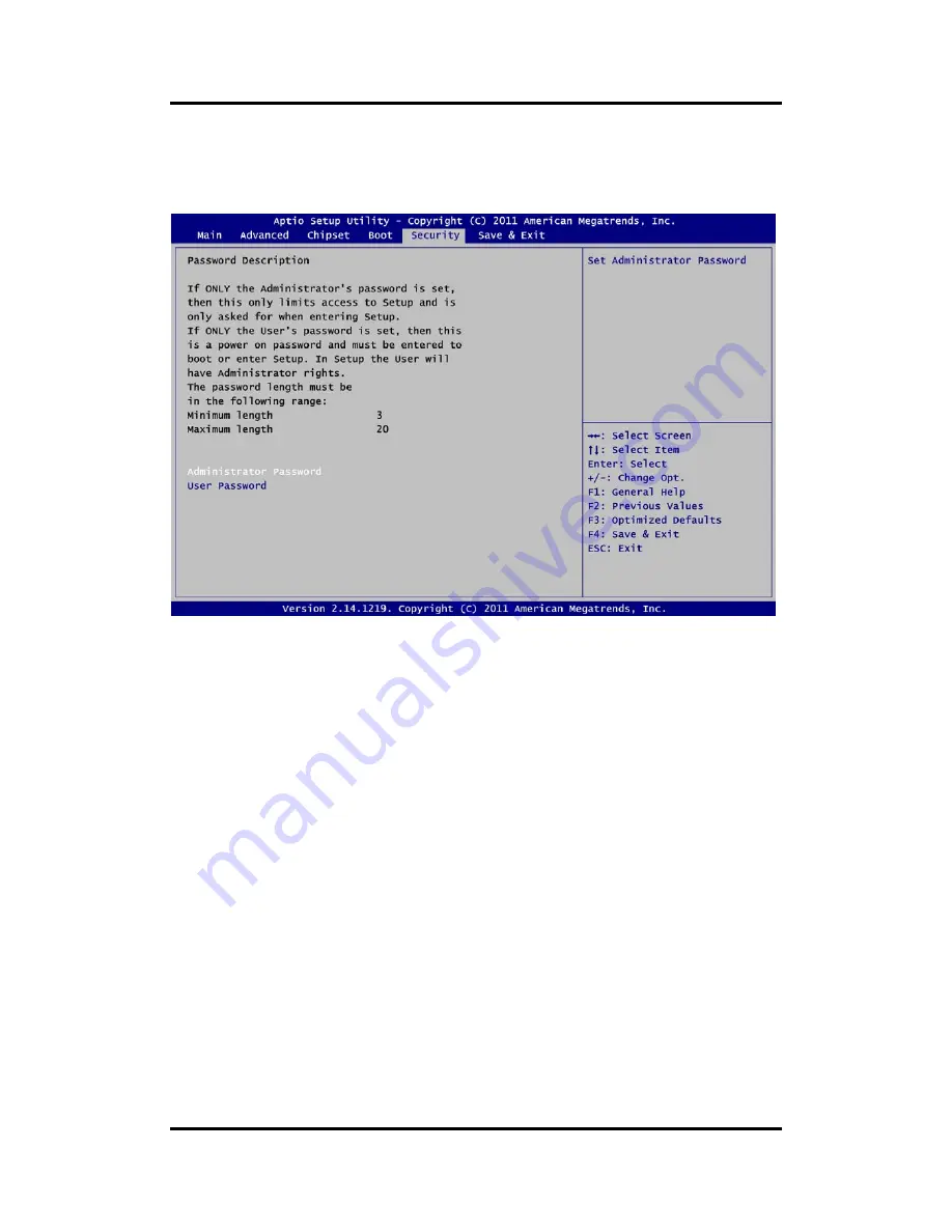
Security Menu
The Security menu allows users to change the security settings for the system.
Administrator Password
This item indicates whether an administrator password has been set (installed or
uninstalled).
User Password
This item indicates whether an user password has been set (installed or uninstalled).
Summary of Contents for IFO2225-873 Series
Page 10: ...x This page is intentionally left blank...
Page 15: ...IFO2225 873 Series User s Manual Introduction 5...
Page 72: ...IFO2225 873 Series User s Manual 62 Watchdog Timer This page is intentionally left blank...
Page 74: ...IFO2225 873 Series User s Manual 64 Digital I O This page is intentionally left blank...


