background image

GOT815W-511 User’s Manual 

Introduction 


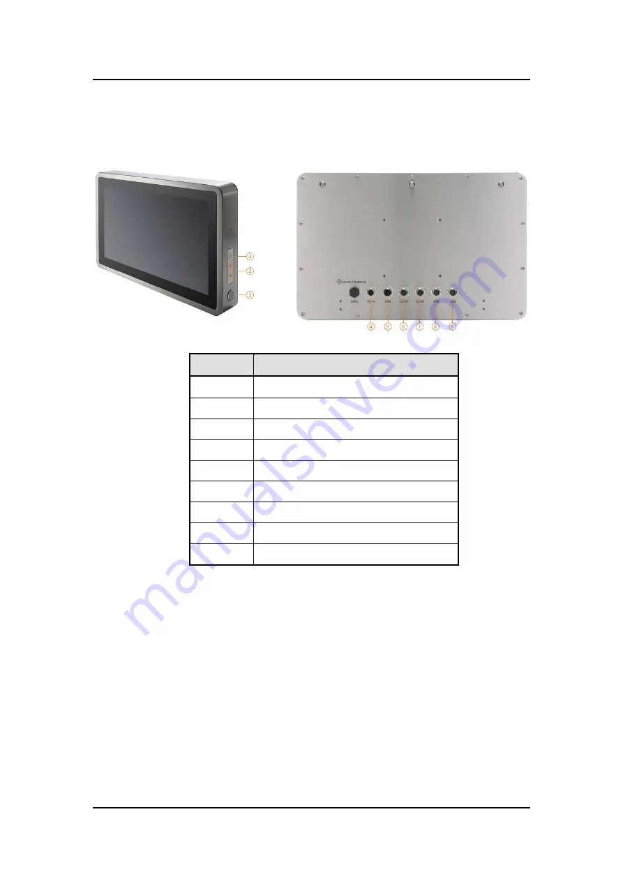
1.4  I/O Outlets 

Please refer to the following illustration for I/O locations of the GOT815W-511. 


No 

Function 

Backlight ON/OFF 

Brightness /- 

Power ON/OFF 

DC Power Connector 

Ethernet 

COM1 (RS-232/422/485, default RS-232) 

COM2 (RS-232/422/485, default RS-232) 

USB 2.0 x 2 

USB 2.0 x 2 


Summary of Contents for GOT815W-511

Page 1: ...GOT815W 511 15 6 FHD TFT Touch Panel Computer User s Manual IP69K certification distinguishes the highest level of reliability...

Page 2: ...usefulness of any information in this document Axiomtek does not make any commitment to update the information in this manual Axiomtek reserves the right to change or revise this document and or produ...

Page 3: ...en you must follow the same procedure and not spray any cleaner on the flat panel directly 6 Avoid using sharp objects to operate the touchscreen Scratches on the touchscreen may cause malfunction or...

Page 4: ...ort 10 2 1 4 DC Power Jack w M12 connector 11 2 2 Water proof Cables 11 2 2 1 Power cable 11 2 2 2 Power adapter for GOT815W 511 12 2 2 3 COM 12 2 2 4 USB cables 13 2 3 Mounting Method 13 2 3 1 VESA m...

Page 5: ...professional yet easy to use panel computer The GOT815W 511 is an ideal for space limited applications in factory automation machine maker operating systems building automation and more GOT815W 511 15...

Page 6: ...default RS 232 4 x USB 2 0 M12 A coded connector x 2 Ethernet One Intel i 210LM Gigabit Ethernet M12 X coded connector Expansion Two Mini PCI E card Full size x 1 Half size x 1 Storage One SATA inter...

Page 7: ...nment please choose the wide temperature DRAM and SSD 3 If the operation temperature is higher than 35 the wide temperature HDD is recommended to be used on the device 4 If the operation temperature i...

Page 8: ...GOT815W 511 User s Manual Introduction 4 1 3 Dimensions This diagram shows you dimensions and outlines of the GOT815W 511...

Page 9: ...r to the following illustration for I O locations of the GOT815W 511 No Function 1 Backlight ON OFF 2 Brightness Adjust 3 Power ON OFF 4 DC Power Connector 5 Ethernet 6 COM1 RS 232 422 485 default RS...

Page 10: ...tallation instructions are as follows 1 If you add optional 2T2R WIFI module the ANT1 is MAIN wifi antenna the ANT2 is AUX wifi antenna 2 If you add optional UMTS HSPA module the ANT1 is main UMTS GSM...

Page 11: ...7 1 6 Package List When you receive the GOT815W 511 the bundled package should contain the following items GOT815W 511 x 1 DC cable x1 If you cannot find the package or any items are missing please co...

Page 12: ...GOT815W 511 User s Manual Introduction 8 This page is intentionally left blank...

Page 13: ...11 has two serial ports COM1 and COM2 RS 232 422 485 default RS 232 two USB ports Ethernet and DC in 12V 24V connecter 2 1 1 Serial Port Interface The following table 1 shows you the pin assignments o...

Page 14: ...face full compliant with IEEE 802 3 standard and can be connected with a M12 LAN connector Please refer to detailed pin assignment list below Pin Signal 1 TX Data transmission positive 2 TX Data trans...

Page 15: ...order each cable base on application There are four kind cables of GOT800 series by the optional if you will apply the USB COM or Ethernet then you can select a cable for the package The Power cable...

Page 16: ...511 If you order the power adapter you should choose the power cord type for your location The power adapter is 110 240V which is combined M12 connector 2 2 3 COM There are two COM cables which are c...

Page 17: ...e USB cable is combined M12 connector for water proof It is extended two USB ports for application 2 3 Mounting Method There are two mounting ways for the GOT815W 511 One is suspension the other is VE...

Page 18: ...Configurations 14 2 3 2 VESA ARM Mounting Step 1 Find out the 4 screws as marked on the back side of chassis Step 2 Assemble the VESA ARM to the back side of the chassis and fix the screws Step 3 VESA...

Page 19: ...n The Up and Down Arrow keys allow you to select a setup screen or sub screen Plus Minus The Plus and Minus Arrow keys allow you to change the field value of a particular setup item Tab The Tab key al...

Page 20: ...Date Time Use this option to change the system time and date Highlight System Time or System Date using the keys Enter new values through the keyboard Press the key or the keys to move between fields...

Page 21: ...any of the items in the left frame of the screen to go to the sub menus Hardware Monitor Utility Configuration Utility Configuration CPU Configuration SATA Configuration PCH FW Configuration USB Conf...

Page 22: ...5W 511 User s Manual 18 AMI BIOS Setup Utility Hardware Monitor This screen monitors hardware health status This screen displays the temperature of system and CPU system voltages VBAT 3 3V 3 3V_SBY an...

Page 23: ...GOT815W 511 User s Manual AMI BIOS Setup Utility 19 Utility Configuration ACPI Settings...

Page 24: ...screen shows the CPU Configuration and you can change the value of the selected option Intel VMX Virtualization Technology Enable or disable Intel Virtualization Technology When enabled a VMM Virtual...

Page 25: ...S Setup Utility 21 SATA Configuration Use this screen to select options for the Super IO Configuration and change the value of the selected option SATA mode selection The SATA mode is set to AHCI mSAT...

Page 26: ...GOT815W 511 User s Manual 22 AMI BIOS Setup Utility PCH FW Configuration This screen displays ME Firmware information USB Configuration...

Page 27: ...ted USB devices BIOS Flash Utility BIOS flash utility configuration For more detailed information please refer to Appendix D AxiomType3 Super IO Configuration A description of selected item appears on...

Page 28: ...tility 3 4 Chipset Menu The Chipset menu allows users to change the advanced chipset settings You can select System Agent SA Configuration in the left frame of the screen to go to the sub menus For it...

Page 29: ...511 User s Manual AMI BIOS Setup Utility 25 Graphics Configuration Use this item to open graphics configuration sub screen Memory Configuration Use this item to refer to information related to system...

Page 30: ...Setup Utility 3 5 Security Menu The Security menu allows users to change the security settings for the system Setup Administrator Password Use this item to set setup administrator password User Passwo...

Page 31: ...11 User s Manual AMI BIOS Setup Utility 27 3 6 Boot Menu The Boot menu allows users to change boot options of the system Bootup NumLock State Use this item to select the power on state for the keyboar...

Page 32: ...disable the boot ROM function of the onboard LAN chip when the system boots up Boot Option Priorities These are settings for boot priority Specify the boot device priority sequence from the available...

Page 33: ...Yes to discard changes and exit Save Changes and Reset When you have completed the system configuration changes select this option to leave Setup and reboot the computer so the new system configurati...

Page 34: ...select this option Select Restore Defaults from the Save Exit menu and press Save as User Defaults Select this option to save system configuration changes done so far as User Defaults Select Save as...

Page 35: ...n of system driver please carefully read the instructions in this chapter before start installing Please download the following GOT815W 511 driver from Axiomtek official website Support Downloads sele...

Page 36: ...511 is designed based on the technology of projected capacitive multi touch screen of which specifications are listed below 4 2 1 Specification Touch Screen 10 point Projected capacitive multi touch...

Page 37: ...4 3 Embedded O S The GOT815W 511 provides the Windows 10 Embedded The O S is supported devices which are listed below WES 10 Here are supported onboard devices Onboard Multi I O SATA HDD USB LCD displ...

Reviews: