AXIOMTEK GOT5840T-834 User Manual Download Page 54

GOT5840T-832 U

ser’s Manual 


AMI BIOS Setup Utility


48 


3.6 

Boot Menu 

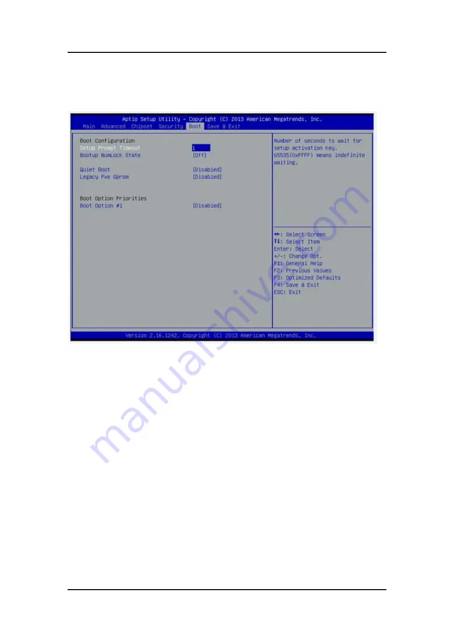
The Boot menu allows users to change boot options of the system. You can select any of the 
items in the left frame of the screen to go to the sub menus:  


Setup Prompt Timeout  

Set the Timeout for wait press key to enter Setup Menu. 
 

Bootup NumLock State  

Use this item to select the power-on state for the NumLock. The default setting is on. 
 

Quiet Boot 

Use this item to enable or disable the Quite Boot state. The default setting is disable. 
 

Legacy Pxe OPROM 

Use  this  item  to  enable  or  disable  the  reboot  Execution  Environment.  The  default  setting  is 
disable. 
 

Boot Option Priorities 

Specifies the overall boot order from the available devices. 

Summary of Contents for GOT5840T-834

Page 1: ...GOT5840T 834 All in One 8 4 SVGA TFT Fanless Touch Panel Computer with Intel Celeron Processor J1900 onboard User s Manual...

Page 2: ...usefulness of any information in this document Axiomtek does not make any commitment to update the information in this manual Axiomtek reserves the right to change or revise this document and or produ...

Page 3: ...the flat panel directly 6 Avoid using sharp objects to operate the touchscreen Scratches on the touchscreen may cause malfunction or internal failure to the touchscreen 7 The flat panel display is no...

Page 4: ...ngs Panel Wall Desktop VESA 23 2 4 1 Panel Mounting 23 2 4 2 Wall Mounting 24 2 4 3 Desktop Mounting 24 2 4 4 VESA ARM Mounting 25 2 5 DRAM Installation 27 2 6 Mini cards Card Installation 29 2 6 1 Wi...

Page 5: ...8S 54 APPENDIX A WATCHDOG TIMER 56 About Watchdog Timer 56 How to Use Watchdog Timer 56 WDT Sample Program 57 APPENDIX B BACKLIGHT CONTROL 60 About Backlight Control 60 How to Use Backlight Control 60...

Page 6: ...vi This page is intentionally left blank...

Page 7: ...make it a professional yet easy to use panel computer The GOT5840T 834 is an ideal for space limited applications in factory automation machine maker operating systems building automation and more GOT...

Page 8: ...pin DDR3L SO DIMM socket Maximum memory up to 8GB 1 2 2 I O System Standard I O 2x RS 232 422 485 2x USB 3 0 Ethernet 2x RJ45 Giga Ethernet Intel i210IT Audio One Line out Expansion 1 x Mini card slot...

Page 9: ...to 50 with W T DRAM CFast or mSATA in airflow condition Relative Humidity 10 to 95 40 Non Condensing Vibration 5 to 500 Hz 2 0 G random for CFast or mSATA Power input 9 36VDC with phoenix power conne...

Page 10: ...GOT5840T 832 User s Manual Introduction 4 1 3 Dimensions This diagram shows you dimensions and outlines of the GOT5840T 834...

Page 11: ...GOT5840T 832 User s Manual Introduction 5...

Page 12: ...3 Power Input connector Screw 7 Dual USB 3 0 ports 4 COM 1 RS 232 422 485 8 AUDIO LINE OUT 1 5 Packing List When you receive the GOT5840T 834 the bundled package should contain the following items GO...

Page 13: ...e hardware It includes CFast Card Serial Port Ethernet Mounting Way DRAM Wireless LAN Card 2 1 CFast card Installation The GOT5840T 834 provides one CFast slot for users to install CFast card Please r...

Page 14: ...GOT5840T 832 User s Manual Hardware Installation 8 2 2 SBC87834 Jumpers and Connectors Component Side...

Page 15: ...GOT5840T 832 User s Manual Hardware Installation 9 Solder Side...

Page 16: ...5V Short 1 2 Short 2 3 JP5 Touch OFF Touch ON Short 1 2 Short 2 3 JP6 PCIe device mSATA device Short 1 2 Short 2 3 JP7 AT mode ATX mode Short 1 2 Short 2 3 JP8 Normal Clear CMOS Short 1 2 Short 2 3 JP...

Page 17: ...system please remember to set this jumper to 2 3 close Restore BIOS Optimal Defaults JP8 Put jumper clip to pin 2 3 for a few seconds then move it back to pin 1 2 Doing this procedure can restore BIO...

Page 18: ...header CN6 SIM card connector CN7 Full size min PCIe connector CN8 DC IN connector CN9 Digital I O pin header CN10 Speaker Out MIC IN connector CN11 VGA connector CN12 Audio connector CN13 USB CONNECT...

Page 19: ...AN2 5 VCC 25 LVDSA_DATAP0 6 VCC 26 LVDSB_DATAP2 7 DDC DATA 27 GND 8 DDC CLOCK 28 GND 9 GND 29 LVDSA_DATAN1 10 GND 30 LVDSA_DATAN3 11 LVDSB_DATAN3 31 LVDSA_DATAP1 12 LVDSB_DATAN0 32 LVDSA_DATAP3 13 LVD...

Page 20: ...LVDS inverter connector CN2 CN2 Pin Assignment Pin Description Pin Description 1 GND 5 Inverter ON OFF 2 GND 6 12V 3 GND 7 12V 4 Backlight control 8 12V TOUCH connector CN3 CN3 Pin Assignment Pin Des...

Page 21: ...power connector CN4 CN9 Pin Assignment Pin Description 1 12V 2 GND 3 GND 4 5V FRONT PANEL pin header CN6 CN6 Pin Assignment Pin Description Pin Description 1 5V 2 Beep 3 GND 4 BUZZER 5 GND 6 Beep 7 NC...

Page 22: ...tion 16 SIM card connector CN7 CN7 Pin Assignment Pin Description Pin Description 1 UIM PWR 5 GND 2 UIM RST 6 UIM VPP 3 UIM CLK 7 UIM DATA 4 NC 8 NC Power connector CN9 CN9 Pin Assignment Pin Descript...

Page 23: ...cription 1 GND 6 GND 2 GPIO0 7 GPIO1 3 GPIO2 8 GPIO3 4 GPIO4 9 GPIO5 5 GPIO6 10 GPIO7 11 GPIO8 12 GPIO9 13 GPIO10 14 GPIO11 15 GPIO12 16 GPIO13 17 GPIO14 18 GPIO15 19 GND 20 GND Speaker Out MIC IN con...

Page 24: ...N12 Pin Assignment USB CONNECTOR reserved CN14 CN20 CN14 CN20 Pin Assignment Pin Description 1 VCC 2 D 3 D 4 GND 5 GND Pin Signal Pin Signal 1 Red 2 GND 3 Green 4 N C 5 Blue 6 N C 7 VCC 8 DDC DATA 9 G...

Page 25: ...ctor CN15 CN15 Pin Assignment Pin Description 1 LINE IN L 2 GND 5 LIN IN R Power lamp connector CN16 CN16 Pin Assignment Pin Description Pin Description 1 Power 5V 2 GND Power button connector CN17 CN...

Page 26: ...ion enable disable LED indicator connector CN18 CN18 Pin Assignment Pin Description 1 ON OFF button 2 GND 3 LED Panel control Keypad connector CN19 CN19 Pin Assignment Pin Description 1 GND 2 Panel ON...

Page 27: ...r USB1 USB1 Pin Assignment Pin Description Pin Description 1 5V 2 5V 3 USB 4 USB 5 USB 6 USB 7 GND 8 GND 9 GND 10 GND Serial Port box header COM3 COM4 COM3 COM4 Pin Assignment Pin Description Pin Desc...

Page 28: ...use No use 7 RTS Request To Send No use No use 8 CTS Clear To Send No use No use 9 RI Ring Indicator No use No use 2 3 Ethernet The GOT5840T 834 is equipped with two high performance Plug and Play Eth...

Page 29: ...ESA There are several mounting ways for the GOT5840T 834 Panel Wall Desktop and VESA mountings 2 4 1 Panel Mounting The GOT5840T 834 is designed for panel mount application A set of standard mounting...

Page 30: ...Wall mounting application Please refer to the following steps Find out the screws as marked on the back side of chassis 2 4 3 Desktop Mounting The GOT5840T 834 is designed for desktop mounting applica...

Page 31: ...tion 25 Step 2 Assemble the desktop stand to the chassis and fix the screws 2 4 4 VESA ARM Mounting Step 1 Find out the screws as marked on the back side of chassis Step 2 Assemble the VESA ARM to the...

Page 32: ...GOT5840T 832 User s Manual Hardware Installation 26 Step 3 VESA mounting Installation completed Caution Use recommended suitable mounting apparatus to avoid risk of injury...

Page 33: ...lation The GOT5840T 834 provides one 204 pin DDR3L SO DIMM socket that support system memory up to 8GB Please follow steps below to install the memory modules Step 1 Unscrew six screws to remove the r...

Page 34: ...ation 28 Step 3 Push down latches on each side of the DIMM socket Step 4 Install the memory module into the socket and push it firmly down until it is fully seated The socket latches are levered upwar...

Page 35: ...ides two Mini card slots for user to install wireless LAN cards You can choose either slot 1 or slot 2 to install the wireless LAN card and refer to the following instructions and illustration Step 1...

Page 36: ...nual Hardware Installation 30 Step 3 Find the built in Antenna cable Step 4 There are two connectors on wireless LAN card One is MAIN and the other is auxiliary Connect antenna cable to MAIN connector...

Page 37: ...ase choose the slot 2 when installing the mSATA card and refer to the following instructions and illustration Step 1 Open the back cover and find out the mini card slot on main board Step 2 Insert the...

Page 38: ...e GOT5840T 834 equips with a phoenix type power connector It adopts 9VDC to 36VDC Please follow the signs on power connector to connect DC power source Power positive G Safety ground Power negative NO...

Page 39: ...wn The Up and Down Arrow keys allow you to select a setup screen or sub screen Plus Minus The Plus and Minus Arrow keys allow you to change the field value of a particular setup item Tab The Tab key a...

Page 40: ...e this option to change the system time and date Highlight System Time or System Date using the Arrow keys Enter new values through the keyboard Press the Tab key or the Arrow keys to move between fie...

Page 41: ...ub menus ACPI Settings NCT6106D Super IO Configuration NCT6106D H W Monitor CPU Configuration IDE Configuration USB configuration Intel TXE Configuration LPSS SCC Configuration For items marked with p...

Page 42: ...MI BIOS Setup Utility 36 ACPI Sleep State Allow you to select the Advanced Configuration and Power Interface ACPI state to be used for system suspend Here are the options for your selection Suspend di...

Page 43: ...e selected option Serial Port 1 4 configuration Serial port This option used to enable or disable the serial port Device Setting This item specifies the base I O port address and Interrupt Request add...

Page 44: ...GOT5840T 832 User s Manual AMI BIOS Setup Utility 38 Serial Type This option used to select RS232 422 485 function...

Page 45: ...GOT5840T 832 User s Manual AMI BIOS Setup Utility 39 NCT6106D H W Monitor This screen shows the Hardware Health Configuration...

Page 46: ...GOT5840T 832 User s Manual AMI BIOS Setup Utility 40 CPU Configuration This screen shows the CPU Configuration and Intel virtualization technology enable disable selected...

Page 47: ...41 IDE Configuration You can use this screen to select options for the SATA Configuration and change the value of the selected option SATA Mode Use this item to choose the SATA operation mode Here are...

Page 48: ...ser s Manual AMI BIOS Setup Utility 42 USB Configuration You can use this screen to select options for the USB Configuration If USB3 0 function used XHCI Mode must enable and EHCI must disable XHCI de...

Page 49: ...Configuration You can select any of the items in the frame of the screen to change the OS the default setting is Win 7 Please be informed to select the Windows 8 x when installing Win 8 or Win 8 1 If...

Page 50: ...GOT5840T 832 User s Manual AMI BIOS Setup Utility 44 Security Configuration The Advanced menu allows users to update the TXE firmware...

Page 51: ...GOT5840T 832 User s Manual AMI BIOS Setup Utility 45 3 4 Chipset Menu The Chipset menu allows users to change the advanced chipset settings...

Page 52: ...GOT5840T 832 User s Manual AMI BIOS Setup Utility 46 North Bridge This screen shows the North Bridge memory information South Bridge...

Page 53: ...GOT5840T 832 User s Manual AMI BIOS Setup Utility 47 3 5 Security...

Page 54: ...imeout for wait press key to enter Setup Menu Bootup NumLock State Use this item to select the power on state for the NumLock The default setting is on Quiet Boot Use this item to enable or disable th...

Page 55: ...GOT5840T 832 User s Manual AMI BIOS Setup Utility 49 3 7 Save Exit This page is intentionally left blank...

Page 56: ...installing 4 1 1 Win 7 1 Insert Driver CD and select the Drivers 2 Select all files and follow the installing procedure NOTE Please install Microsoft KB2685811 before TXE installation under Windows 7...

Page 57: ...een The GOT5840T 834 uses the 5 wire analog resistive There are the specification and driver installation which are listed below 4 2 1 Specification Touch Screen 5 wire Analog Resistive type Touch Scr...

Page 58: ...ng system Windows 7 8 1 To facilitate installation of the touch screen driver you should read the instructions in this chapter carefully before you attempt installation 1 Insert Driver CD and follow t...

Page 59: ...s Installation 53 4 Select the Standard Calibrate tab 5 Calibration To adjust the display with touch panel click Calibration and follow the calibrate point to do calibration there are five points on s...

Page 60: ...HDD USB CRT LCD display 10 100 1000 base T Ethernet CFast TM or mSATA Onboard Audio Touch Screen PenMount Touch screen Before you can use and calibrate it here is what you should do 1 Set up Penmount...

Page 61: ...GOT5840T 832 User s Manual Drivers Installation 55 This page is intentionally left blank...

Page 62: ...e and must reset it periodically If the counter ever reaches zero which means the software has crashed the system will reboot How to Use Watchdog Timer The I O port base addresses of watchdog timer ar...

Page 63: ...DT Device Enable O 2E 30 O 2F 01 4 Set timer unit O 2E F0 O 2F 00 00 Sec 08 Minute 5 Set base timer O 2E F1 O 2F 0A Set Reset Time Ex 0A 10 Sec Disable WDT 1 Enable configuration O 2E 87 O 2E 87 2 Sel...

Page 64: ...GOT5840T 832 User s Manual 58 Watchdog Timer...

Page 65: ...GOT5840T 832 User s Manual Watchdog Timer...

Page 66: ...people can adjust the panel backlight depending on your personal taste and the amount of ambient light in the room after installing the backlight control tool How to Use Backlight Control Step 1 Acco...

Page 67: ...GOT5840T 832 User s Manual Backlight Control 61...

Page 68: ...GOT5840T 832 User s Manual Backlight Control 62 Step 2 Follow the installing procedures and press Close...

Page 69: ...GOT5840T 832 User s Manual Backlight Control 63...

Page 70: ...GOT5840T 832 User s Manual Backlight Control 64...

Page 71: ...GOT5840T 832 User s Manual Backlight Control 65...

Page 72: ...GOT5840T 832 User s Manual Backlight Control 66...

Page 73: ...GOT5840T 832 User s Manual Backlight Control 67...

Page 74: ...Step 4 Select icon then find out the Axiomtek to ensure the brightness driver is installed appropriately Step 5 How to use the brightness Control There are two ways to adjust the display brightness S...

Page 75: ...GOT5840T 832 User s Manual Backlight Control 69 Step 5 2 Click the Control Panel then select Power Options to adjust the display brightness...

Page 76: ...ual Backlight Control 70 Removed Brightness Control Tool Step 1 According to the OS version please insert the driver CD and follow the path to select the proper driver Driver Win8 x Step 8 Setup or Dr...

Page 77: ...GOT5840T 832 User s Manual Backlight Control 71 Step 2 Follow the procedures and press Close...

Page 78: ...GOT5840T 832 User s Manual Backlight Control 72...

Page 79: ...GOT5840T 832 User s Manual Backlight Control 73 Step 3 System auto reboot uninstallation completed...

Reviews: