background image

GOT3846T-832 U

ser’s Manual 

Hardware Installation 

16 

2.5 

Mountings: Panel / Wall / Desktop / VESA 

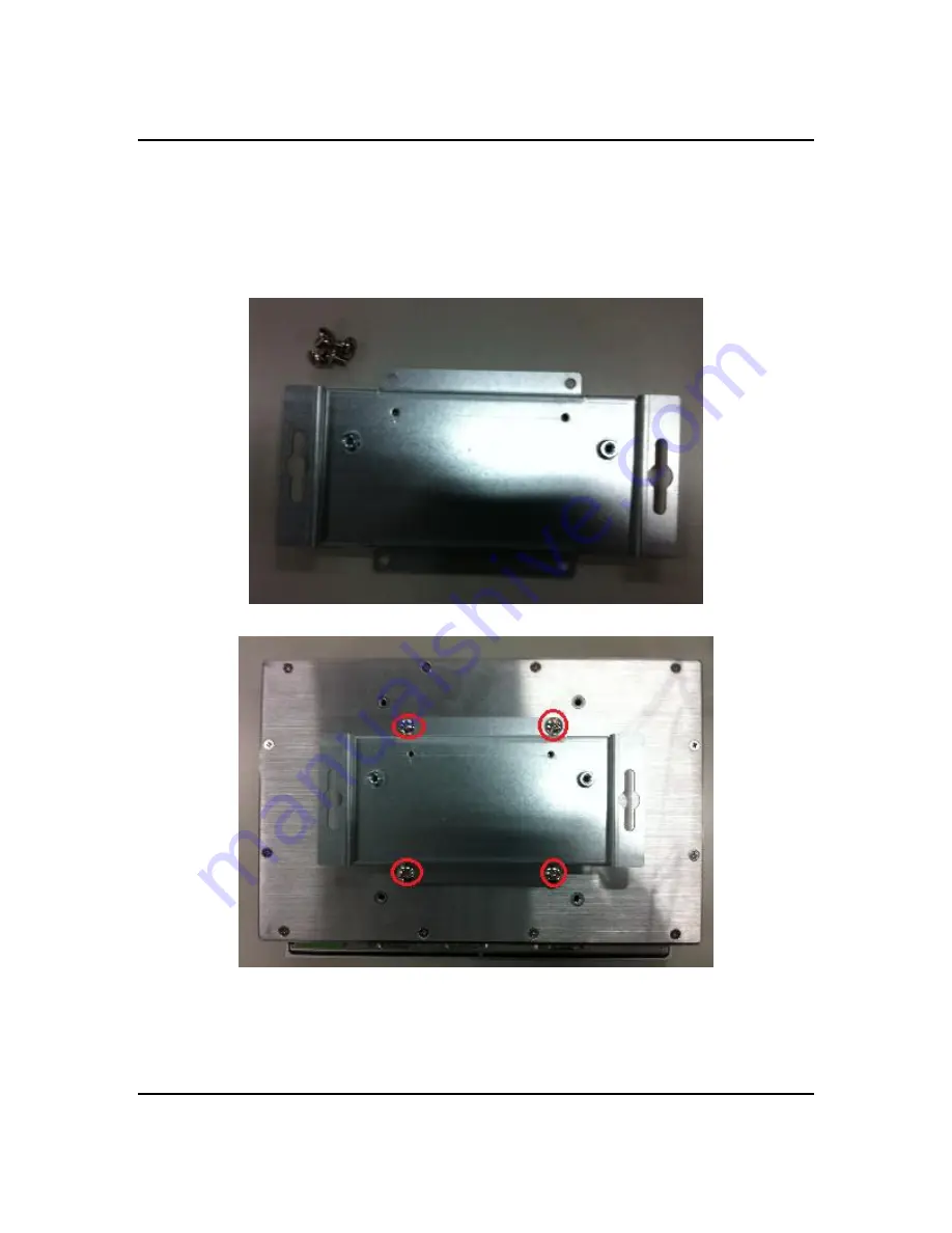
There are 4 application options for the GOT3846T-832, Panel/Wall/Desktop/VESA mountings. 

2.5.1 

VESA-ARM/Wall-Mount 

The  GOT3846T-832  provides  VESA  mount:  75x75  mm .  Screw  four  screws  to  fix  the  kit 
in the back chassis.  


Summary of Contents for GOT3846T-832

Page 1: ...GOT3846T 832 All in One 8 4 SVGA TFT Fanless Compact Size PANEL PC User s Manual...

Page 2: ...usefulness of any information in this document Axiomtek does not make any commitment to update the information in this manual Axiomtek reserves the right to change or revise this document and or prod...

Page 3: ...you must follow the same procedure and not spray any cleaner on the flat panel directly 6 Avoid using sharp objects to operate the touchscreen Scratches on the touchscreen may cause malfunction or in...

Page 4: ...3 2 COM3 COM4 Connector 14 2 4 Ethernet 15 2 5 Mountings Panel Wall Desktop VESA 16 2 5 1 VESA ARM Wall Mount 16 2 5 2 Panel mount Kit Assembly 17 2 6 HDD Installation 18 2 7 DRAM Installation 21 2 8...

Page 5: ...uction 1 CHAPTER 1 INTRODUCTION This chapter contains general information and detailed specifications of the GOT3846T 832 Chapter 1 includes the following sections General Description Specification Di...

Page 6: ...he GOT3846T 832 adopts a fan less cooling system which makes it especially suitable for vibration heavy environments best for the transportation ship and industrial machinery markets For high capacity...

Page 7: ...BIOS America Megatrends BIOS System Memory One 204 pin DDR3 800MHz SO DIMM socket Maximum memory up to 2GB 1 2 2 I O System Standard I O 1 x RS 232 422 485 3 x RS232 4x USB 2 0 1x VGA Ethernet 2x RJ4...

Page 8: ...ng One 2 5 SATA drive Net Weight 3 4 Kgs 7 49 lb Dimension Main Body Size 248x 58 3x 183mm Operation Temperature 20 to 55 Relative Humidity 10 to 95 40 Non Condensing Power input 10 30VDC with phoenix...

Page 9: ...GOT3846T 832 User s Manual Introduction 5 1 3 Dimensions The following diagrams show the dimensions and outlines of GOT3846T 832...

Page 10: ...GOT3846T 832 User s Manual Introduction 6...

Page 11: ...GOT3846T 832 User s Manual Introduction 7 1 4 I O Outlets Please refer to the following illustration for I O locations of the GOT3846T 832...

Page 12: ...846T 832 the bundled package should contain the following items GOT3846T 832 unit x 1 Driver CD x1 Phoenix connector x 1 Panel mount kit x 6 Wall mount Kit x 1 Screws for HDD x 4 If you can not find t...

Page 13: ...ATION The GOT3846T 832 provides rich I O ports and flexible expansions for you to meet different demand for example CF card The chapter will show you how to install the hardware It includes CompactFla...

Page 14: ...l Hardware Installation 10 2 1 Open back cover This section tells users how to open back cover Please follow the steps below Step 1 Unscrew 12 screws on the back cover Please refer the photo below Ste...

Page 15: ...ual Hardware Installation 11 2 2 CF card Installation The GOT3846T 832 provides one CF slot for users to install CompactFlash card Please refer to the following instructions for installation Step 1 Un...

Page 16: ...GOT3846T 832 User s Manual Hardware Installation 12 Step 2 Remove the chassis Step 3 Insert the card into the socket...

Page 17: ...erface The GOT3846T 832 has four serial ports COM1 is RS 232 422 485 while COM2 COM3 and COM4 are RS 232 The following table shows you the pin assignments of this connector Description Function Jumper...

Page 18: ...1 5 6 10 2 3 2 COM3 COM4 Connector The COM3 and COM4 is a 2x5 pin box header This connector is equipped with 5V level power capability on DCD and 12V level on RI by setting JP12 and JP13 The pin assi...

Page 19: ...ompliant with IEEE 802 3 standard and can be connected with a RJ 45 LAN connector Please refer to detailed pin assignment list below Pin Signal 1 2 3 4 5 6 7 8 RJ 45 1 TX Data transmission positive 2...

Page 20: ...2 5 Mountings Panel Wall Desktop VESA There are 4 application options for the GOT3846T 832 Panel Wall Desktop VESA mountings 2 5 1 VESA ARM Wall Mount The GOT3846T 832 provides VESA mount 75x75 mm Sc...

Page 21: ...s Manual Hardware Installation 17 2 5 2 Panel mount Kit Assembly The GOT3846T 832 is designed for panel mount application To mount the GOT3846T 832 the standard set of mounting kit included in the sys...

Page 22: ...on The GOT3846T 832 provides a convenient Hard Disk Drive HDD bracket for users to install 2 5 SATA HDD Please follow the steps Step 1 Refer section 2 1 to open the back cover Step 2 Unscrew 4 screws...

Page 23: ...846T 832 series User s Manual Hardware Installation 19 Step 4 Fix the HDD bracket into the cover fasten the power and data cable in the cable tie then plug the cables to connectors Installation comple...

Page 24: ...GOT3846T 832 User s Manual Hardware Installation 20 Data Powe r...

Page 25: ...des one 204 pin DDR3 SODIMM socket that support system memory up to 2GB Please follow steps below to install the memory modules Step 1 Refer to section 2 1 to open the back cover and find out DIMM soc...

Page 26: ...GOT3846T 832 User s Manual Hardware Installation 22 Step 3 Insert the DRAM to the DIMM socket and then push it down firmly until it is clipped by the socket...

Page 27: ...GOT3846T 832 series User s Manual Hardware Installation 23 Step 4 Rip the red mylar from DRAM bracket then screw it into the chassis Installation completed...

Page 28: ...GOT3846T 832 User s Manual Hardware Installation 24...

Page 29: ...d slot for user to install one wireless LAN card When installing the wireless LAN card refer to the following instructions and illustration Step 1 Refer to section 2 1 to open the back cover and find...

Page 30: ...Step 3 Find the built in Antenna cable and connect it wireless LAN card Step 4 Lift the rubber stopper from the top of back cover Step 5 Install the antenna on the antenna connector NOTE Please have...

Page 31: ...846T 832 equips with a phoenix type power connector It adopts 10VDC to 30VDC Please follow the signs on power connector to connect DC power source Power positive G Safty ground Power negative NOTE The...

Page 32: ...GOT3846T 832 User s Manual Hardware Installation 28 MEMO...

Page 33: ...up basic system configuration through the AMIBIOS8 BIOS setup utility 3 1 Starting To enter the setup screens follow the steps below Turn on the computer and press the Del key immediately After you pr...

Page 34: ...u to select a setup screen or sub screen Plus Minus The Plus and Minus Arrow keys allow you to change the field value of a particular setup item Tab The Tab key allows you to select setup fields F1 Th...

Page 35: ...tab There are two Main Setup options They are described in this section The Main BIOS Setup screen is shown below System Time Date Use this option to change the system time and date Highlight System T...

Page 36: ...n for legacy mass storage devices with Option ROM The Advanced menu allows users to set configuration of the CPU and other system devices You can select any of the items in the left frame of the scree...

Page 37: ...You can use this screen to select options for the ACPI Settings and change the value of the selected option A description of the selected item appears on the right side of the screen ACPI Sleep State...

Page 38: ...change the value of the selected option Hyper Threading Technology Use this item to enable or disable Hyper Threading Technology which makes a single physical processor perform multi tasking function...

Page 39: ...GOT3846T 832 series User s Manual AMI BIOS Setup Utility 35 IDE Configuration SATA Controller s The optional settings are Disabled Enabled Configure SATA as The optional settings are IDE AHCI...

Page 40: ...guration You can use this screen to select options for the USB Configuration and change the value of the selected option A description of the selected item appears on the right side of the screen Lega...

Page 41: ...nfiguration You can use this screen to select options for the Super IO Configuration and change the value of the selected option A description of the selected item appears on the right side of the scr...

Page 42: ...GOT3846T 832 User s Manual AMI BIOS Setup Utility 38 PC Health Status This screen shows the Hardware Health Configuration and a description of the selected item appears on the right side of the screen...

Page 43: ...users to change the advanced chipset settings You can select any of the items in the left frame of the screen to go to the sub menus Host Bridge Host Bridge For items marked with please press Enter f...

Page 44: ...GOT3846T 832 User s Manual AMI BIOS Setup Utility 40 Memory Frequency and Timing This item is for memory frequency and timing settings Press Enter to go to the sub menu...

Page 45: ...settings are On Off GateA20 Active If Upon Request is selected GA20 can be disabled using BIOS services If Always is selected disabling G20 is not allowed this option is useful when any RT code is exe...

Page 46: ...he system Administrator Password This item indicates whether an administrator password has been set If the password has been installed Installed displays If not Not Installed displays User Password Th...

Page 47: ...rom the Exit menu and press Enter Select Ok to save changes and exit Discard Changes and Exit Select this option to quit Setup without making any permanent changes to the system configuration Select D...

Page 48: ...changes to the system configuration Select Discard Changes from the Save Exit menu and press Enter Select Yes to discard changes Restore Defaults It automatically sets all Setup options to a complete...

Page 49: ...ION 4 1 System GOT3846T 832 supports Windows 7 32 bit and WES 7 To facilitate the installation of system driver please carefully read the instructions in this chapter before start installing 1 Insert...

Page 50: ...ng system Windows 7 To facilitate installation of the touch screen driver you should read the instructions in this chapter carefully before you attempt installation 1 Insert Driver CD and follow the p...

Page 51: ...GOT3846T 832 series User s Manual Installation of Drivers 47 3 Click Start menu and select PenMount Utilities and then a PenMount Control Panel pops out 4 Select the Standard Calibrate tab...

Page 52: ...r s Manual Installation of Drivers 48 5 Calibration To adjust the display with touch panel click Calibration and follow the calibrate point to do calibration there are five points on screen for calibr...

Page 53: ...2 Keyboard and mouse CRT LCD display 10 100 1000 base T Ethernet Compact Flash Onboard Audio Touch Screen PenMount Touch screen Before you can use and calibrate it here is what you should do 1 Set up...

Page 54: ...GOT3846T 832 User s Manual Installation of Drivers 50 MEMO...

Reviews: