


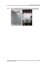


GOT115-319
User’s Manual
8
Hardware and Installation
Diagram 2-2 Solder side of the board
2.1.1 Jumper Settings
By making proper jumper settings, users can configure the board
SBC87319
to suit the needs
of their applications.
Table 2-1 shows the default jumper settings for the SBC87319.
Table 2-1 Default jumper settings
Jumper
★
Default Setting
Jumper Setting
JP3
★
Normal
Clear CMOS
Short 1-2
Short 2-3
JP2
★
LVDS Panel Power : 3.3V
LVDS Panel Power : 5V
Short 1-2
Short 2-3
NOTE: Items marked with
★
are for default settings.
Summary of Contents for GOT115-319
Page 6: ...vi This page is intentionally left blank ...
Page 10: ...GOT115 319 User s Manual 4 Introduction 1 3 Dimensions GOT115 319 outlines and dimensions ...
Page 50: ...GOT115 319 User s Manual 44 Watchdog Timer DIO Programming ...
Page 51: ...GOT115 319 User s Manual Watchdog Timer DIO Programming 45 ...