eBOX640-521-FL Series U
ser’s Manual
Jumper & Connector Settings
22
3.3.1 DC Jack Power Connector (CN1)
The CN1 is a DC jack with screw supporting the 12V, 19-
24VDC power input connector. Firmly insert an adapter
with at least 90W power supply into this connector. Loose
connection may cause system instability and make sure all
components/devices
are
properly
installed
before
connecting.
【
Note
】
Screw metric thread size: M8.0x0.75.
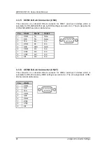
3.3.2 USB 2.0 Stack Port (CN2)
The motherboard comes with one stacked Universal Serial Bus (compliant with USB
2.0) connector on the rear I/O for installing USB peripherals such as a keyboard,
mouse, scanner, etc.
3.3.3 USB 3.0 Stack Port (CN3)
The motherboard comes with one stacked Universal Serial Bus (compliant with USB 3.0)
connector on the rear I/O for installing USB peripherals such as a keyboard, mouse, scanner,
etc.
Pins
Signals
Pins
Signals
1
USB_PWR
2
USB_PWR
3
USB#5_D-
4
USB#6_D-
5
USB#5_D+
6
USB#6_D+
7
GND
8
GND
Pins
Signals
Pins
Signals
1
USB_PWR
10
USB_PWR
2
USB#1_D-
11
USB#2_D-
3
USB#1_D+
12
USB#2_D+
4
GND
13
GND
5
SSRX1-
14
SSRX2-
6
SSRX1+
15
SSRX2+
7
GND
16
GND
8
SSTX1-
17
SSTX2-
9
SSTX1+
18
SSTX2+
Summary of Contents for eBOX640-521-FL Series
Page 1: ...eBOX640 521 FL Series Embedded System User s Manual ...
Page 13: ...eBOX640 521 FL Series User s Manual Introduction 5 1 3 2 Wall mount Bracket Dimensions ...
Page 43: ...eBOX640 521 FL Series User s Manual BIOS Setup Utility 35 ...
Page 62: ...eBOX640 521 FL Series User s Manual 54 Watchdog Timer This page is intentionally left blank ...
Page 71: ...eBOX640 521 FL Series User s Manual TPM Settings 63 ...

