background image

eBOX626-311-FL U

ser’s Manual 

Jumper Setting & Connector 


32 


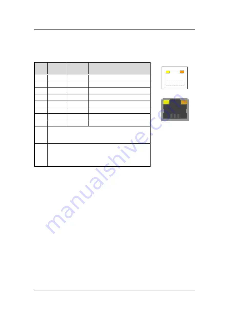
3.3.7  Ethernet Ports (LAN1 and LAN2) 

The  system  supports  two  RJ-45  connectors:  LAN1  and  LAN2.  Ethernet  connection  can  be 
established by plugging one end of the Ethernet cable into this RJ-45 connector and the other 
end (phone jack) to a 1000/100/10-Base-T hub. 


A


B


L1

L2

L3

L4

L5

L6

L7

L8

A

B

Pins 

1000 

Base-T 

100/10 

Base-T 

Descriptions 

L1 

BI_DA+ 

TX+ 

Bidirectional or Transmit Data+ 

L2 

BI_DA- 

TX- 

Bidirectional or Transmit Data- 

L3 

BI_DB+ 

RX+ 

Bidirectional or Receive Data+ 

L4 

BI_DC+ 

N.C. 

Bidirectional or Not Connected 

L5 

BI_DC- 

N.C. 

Bidirectional or Not Connected 

L6 

BI_DB- 

RX- 

Bidirectional or Receive Data- 

L7 

BI_DD+ 

N.C. 

Bidirectional or Not Connected 

L8 

BI_DD- 

N.C. 

Bidirectional or Not Connected 

Active Link LED (Yellow) 

Off: No link 

Blinking: Data activity detected 

Speed LED 

1000: Orange  

100: Green 

10: OFF 

Summary of Contents for eBOX626-311-FL

Page 1: ...eBOX626 311 FL Embedded System User s Manual...

Page 2: ...usefulness of any information in this document Axiomtek does not make any commitment to update any information in this manual Axiomtek reserves the right to change or revise this document and or prod...

Page 3: ...source is correct before connecting the equipment to the power outlet 5 Turn OFF the system power before cleaning Clean the system using a cloth only Do not spray any liquid cleaner directly onto the...

Page 4: ...presence of a flammable anesthetic mixture with air or with oxygen or nitrous oxide 4 Mode of operation Continuous Note All of I O connectors should be connected with corresponding cables when the sy...

Page 5: ...e components in your computer may only be able to be cleaned using a product designed for cleaning that component if this is the case it will be mentioned in the cleaning Cloth A piece of cloth is the...

Page 6: ...ecycling and we will make the proper arrangement Trademarks Acknowledgments Axiomtek is a trademark of Axiomtek Co Ltd IBM PC AT VGA HDMI are trademarks of International Business Machines Corporation...

Page 7: ...f the 2 5 SATA Device 18 SECTION 3 JUMPER SETTING CONNECTOR 23 3 1 CAPA311 layout 23 3 2 Jumper Setting Summary 25 3 2 1 Restore BIOS Optimal Defaults JP3 26 3 2 2 COM3 Data Power Selection JP4 26 3 2...

Page 8: ...viii 4 5 Chipset Menu 51 4 6 Security Menu 54 4 7 Boot Menu 55 4 8 Save Exit Menu 56 APPENDIX A WATCHDOG TIMER 59 A 1 About Watchdog Timer 59 A 2 How to Use Watchdog Timer 59...

Page 9: ...GB of memory In addition for enhanced security the eBOX626 311 FL supports TPM 1 2 It also supports Axiomtek s exclusive AXView Industrial IoT software for smart device monitoring and management It is...

Page 10: ...dded O S Supported The eBOX626 311 FL supports Windows 10 IoT Linux and AXView 3 0 Various Storage Supported In terms of storage the eBOX626 311 FL supports one 2 5 SATA storage drive bay and one mSAT...

Page 11: ...Express Mini Card Slots USB PCI Express mSATA signal 1 x full size PCI Express Mini Card Slots USB PCI Express signal 1 x SIM slot Storage 1 x 2 5 SATA HDD SSD drive bay 1 x mSATA enabled in BIOS sett...

Page 12: ...0 F 140 F with W T SSD DRAM Storage Temperature 40 80 40 F 176 F Humidity 10 95 non condensation Vibration Endurance IEC 60068 2 27 with SSD 3Grms STD random 5 to 500 Hz 1 hr axis Shock Endurance IEC...

Page 13: ...eBOX626 311 FL User s Manual Introduction 5 1 3 Dimensions The following diagrams show you dimensions and outlines of the eBOX626 311 FL 1 3 1 System Dimension...

Page 14: ...eBOX626 311 FL User s Manual Introduction 6 1 3 2 Wall mount Bracket Dimension Screw M3x6L 4pcs...

Page 15: ...eBOX626 311 FL User s Manual Introduction 7 1 3 3 Din rail mount Bracket Dimension Screw M3x6L 4pcs M3x4L 2pcs...

Page 16: ...eBOX626 311 FL User s Manual Introduction 8 1 3 4 VESA mount Bracket Dimension Screw M3x6L 4pcs...

Page 17: ...eBOX626 311 FL User s Manual Introduction 9 1 4 I O Outlets The following figures show you I O outlets on front view of the eBOX626 311 FL Front View Front View drawing...

Page 18: ...eBOX626 311 FL User s Manual Introduction 10 Rear View Rear View drawing...

Page 19: ...ews Pack x 1 Pre installed Foot pad x 4 DRAM Thermal Pad x 1 HDMI Cable Locking Clip optional power adapter optional Power cord optional If you cannot find this package or any items are missing please...

Page 20: ...eBOX626 311 FL User s Manual Introduction 12 This page is intentionally left blank...

Page 21: ...ory Module HDD Hard Disk Drive SSD Solid State Drive and mini card slot The chapter 2 will show you how to install the hardware 2 1 Installing of the Memory module Step 1 Turn off the system and unplu...

Page 22: ...eBOX626 311 FL User s Manual Hardware Installation 14 Step 4 Locate the DDR3L SO DIMM slot and apply the thermal pad on the DDR3L SO DIMM slot...

Page 23: ...DIMM at a 30 degree angle up from horizontal slowly insert the golden fingers into the DDR3L SO DIMM slot until it is fully inserted in Step 6 Press it down gently until it is firmly seated by lockin...

Page 24: ...6 2 2 Installing of the PCI Express Mini Card Step 1 Turn off the system and unplug the power cord Step 2 Turn the system upside down to locate screws at the side of the system and then loosen one scr...

Page 25: ...ot on the board Step 5 Holding the PCI Express mini card at a 45 degree angle up from horizontal slowly insert the golden fingers into the PCI Express slot until it is fully inserted in and fasten scr...

Page 26: ...TA Device Step 1 Turn off the system and unplug the power cord Step 2 Turn the system upside down to locate screws at the side of the system and then loosen one screw and four foot pads Step 3 Please...

Page 27: ...eBOX626 311 FL User s Manual Hardware Installation 19 Step 4 Assemble the HDD SSD with the bracket by two M3 4L screws...

Page 28: ...eBOX626 311 FL User s Manual Hardware Installation 20 Step 5 Locate the HDD SSD tray location and follow the three locating pins to assemble the HDD SSD...

Page 29: ...nstallation 21 Step 6 Connect the power cable and SATA cable with HDD SSD and affix it with two M3 4L screws Note Please notice the direction of connector and locating pins for HDD SSD Step 7 Put the...

Page 30: ...eBOX626 311 FL User s Manual Hardware Installation 22 This page is intentionally left blank...

Page 31: ...plication purpose We are herewith listing a summary table of all jumpers and default settings for onboard devices respectively 3 1 CAPA311 layout Top View Side View Note We strongly recommended that y...

Page 32: ...eBOX626 311 FL User s Manual Jumper Setting Connector 24 Bottom View...

Page 33: ...devices respectively Jumper and Switch Description Setting JP3 Restore BIOS Optimal Defaults Default Normal Operation 1 2 Close JP4 COM3 Data Power Selection Default RS 232 Data CN4 Pin 1 DCD 3 5 Clo...

Page 34: ...ing jumper JP4 3 2 3 AT ATX Quick Switch SSW1 If SSW1 is enabled for power input the system will be automatically power on without pressing soft power button If SSW1 is disabled for power input it is...

Page 35: ...FL Series Connectors Buttons Location Section VGA Connector CN23 3 3 1 COM Serial Port Connector COM1 3 CN17 CN18 CN4 3 3 2 USB 2 0 Wafer Port CN7 3 3 3 SATA Connector CN15 3 3 4 HDMI Connector CN19 3...

Page 36: ...s RS 232 ports Please refer to Chapter 4 for the detail of BIOS setting COM1 and COM2 CN17 and CN18 Pin RS 232 RS 422 RS 485 1 DCD Data Carrier Detect TX Data 2 RXD Receive Data TX Data 3 TXD Transmit...

Page 37: ...B 2 0 480Mbps connector on the rear I O It is commonly used for installing USB peripherals such as keyboard mouse scanner etc 3 3 4 SATA Connector CN15 This Serial Advanced Technology Attachment Seria...

Page 38: ...smitting high definition video and high resolution audio over a single cable Its interface is available through connector CN19 Pin Signal Pin Signal 1 HDMI OUT_DATA2 2 GND 3 HDMI OUT_DATA2 4 HDMI OUT_...

Page 39: ...nner etc USB 3 0 port 0 and 1 CN20 USB 3 0 port 2 and 3 CN21 Pin Signal Pin Signal 1 USB_VCC 5V 10 USB_VCC 5V 2 USB 0_D 11 USB 1_D 3 USB 0_D 12 USB 1_D 4 GND 13 GND 5 SSRX0 14 SSRX1 6 SSRX0 15 SSRX1 7...

Page 40: ...L3 L4 L5 L6 L7 L8 A B Pins 1000 Base T 100 10 Base T Descriptions L1 BI_DA TX Bidirectional or Transmit Data L2 BI_DA TX Bidirectional or Transmit Data L3 BI_DB RX Bidirectional or Receive Data L4 BI_...

Page 41: ...n Signal 1 WAKE 2 3 3VSB 3 No use 4 GND 5 No use 6 1 5V 7 CLKREQ 8 SIM_PWR 9 GND 10 SIM_DATA 11 REFCLK 12 SIM_CLK 13 REFCLK 14 SIM_REST 15 GND 16 SIM_VPP 17 No use 18 GND 19 No use 20 W_DISABLE 21 GND...

Page 42: ...stem has SCN2 socket on the bottom side for inserting SIM Card In order to work properly the SIM Card must be used together with 3G LTE module which is inserted to SCN1 or SCN3 It is mainly used in 3G...

Page 43: ...to section 4 4 to change the setting Pin Signal Pin Signal 1 WAKE 2 3 3VSB 3 No use 4 GND 5 No use 6 1 5V 7 CLKREQ 8 SIM_PWR 9 GND 10 SIM_DATA 11 REFCLK 12 SIM_CLK 13 REFCLK 14 SIM_REST 15 GND 16 SIM...

Page 44: ...lights up and will remain steady while the system is powered on 3 3 12 System Power Switch This button is for turning on off the system power 3 3 13 DC in Phoenix Power Connector The system supports 9...

Page 45: ...setup navigation process These keys include F1 F2 Enter ESC Arrow keys and so on NOTE Some of the navigation keys differ from one screen to another Hot Keys Description Left Right The Left and Right A...

Page 46: ...up as described below The Main BIOS setup screen is shown below Project Version Information Display the auto detected BIOS information System Date Time Use this option to change the system time and d...

Page 47: ...guration of the CPU and other system devices You can select any of the items in the left frame of the screen to go to the sub menus Hardware Monitor ACPI Settings Trusted Computing Super IO Configurat...

Page 48: ...6 311 FL User s Manual BIOS Setup Utility 40 Hardware Monitor This screen monitors hardware health status This screen displays the temperature of system and CPU and system voltages VBAT 3 3V 3 3VSB an...

Page 49: ...gs ACPI Sleep State Select the ACPI Advanced Configuration and Power Interface sleep state Configuration options are Suspend Disabled and S3 Suspend to RAM The S3 Suspend to RAM option selects ACPI sl...

Page 50: ...TPM settings Security Device Support Enable or disable BIOS support for security device The default setting is Enable TPM Device Enable or disable TPM device Pending Operation Schedule a TPM operation...

Page 51: ...ions for the Super IO Configuration and change the value of the selected option A description of the selected item appears on the right side of the screen For items marked with please press Enter for...

Page 52: ...tility 44 Serial Port 1 COM1 Configuration Serial Port Enable or disable serial port 1 The optimal setting for base I O address is 3F8h and for interrupt request address is IRQ4 COM Port Type Use this...

Page 53: ...tility 45 Serial Port 2 COM2 Configuration Serial Port Enable or disable serial port 2 The optimal setting for base I O address is 2F8h and for interrupt request address is IRQ3 COM Port Type Use this...

Page 54: ...up Utility 46 Serial Port 3 COM3 Configuration Serial Port Enable or disable serial port 3 The optimal setting for base I O address is 3E8h and for interrupt request address is IRQ11 COM Port Type Use...

Page 55: ...y 47 CPU Configuration This screen shows the CPU Configuration Intel Virtualization Technology Allow a hardware platform to run multiple operating systems separately and simultaneously enabling one sy...

Page 56: ...Manual BIOS Setup Utility 48 Turbo Mode This item is for enabling or disabling turbo mode When enabled it allows processor cores to run faster than marked frequency under certain conditions The defaul...

Page 57: ...the presence of SATA devices Chipset SATA Enable or disable Chipset Controller feature The default is Enabled PCIE Mini Card Function Select PCI Express Mini Card or mSATA support for SCN3 The defaul...

Page 58: ...eBOX626 311 FL User s Manual BIOS Setup Utility 50 USB Configuration USB Devices Display all detected USB devices...

Page 59: ...Chipset Menu The Chipset menu allows users to change the advanced chipset settings You can select any of the items in the left frame of the screen to go to the sub menus North Bridge South Bridge For...

Page 60: ...eBOX626 311 FL User s Manual BIOS Setup Utility 52 North Bridge Memory Information Display system memory information...

Page 61: ...eBOX626 311 FL User s Manual BIOS Setup Utility 53 South Bridge This screen allows users to configure parameters of South Bridge chipset...

Page 62: ...menu allows users to change the security settings for the system Setup Administrator Password This item indicates whether an administrator password has been set installed or uninstalled User Password...

Page 63: ...the power on state for the keyboard NumLock Quiet Boot Select to display either POST output messages or a splash screen during boot up Launch UEFI PXE OpROM policy Use this item to enable or disable t...

Page 64: ...Yes to save changes and exit Discard Changes and Exit Select this option to quit Setup without making any permanent changes to the system configuration and return to Main Menu Select Discard Changes a...

Page 65: ...hanges to the system configuration Select Discard Changes from the Save Exit menu and press Enter Select Yes to discard changes Restore Defaults It automatically sets all Setup options to a complete s...

Page 66: ...eBOX626 311 FL User s Manual BIOS Setup Utility 58 This page is intentionally left blank...

Page 67: ...uto reset by the watchdog timer The integrated watchdog timer can be set up in the system reset mode by program A 2 How to Use Watchdog Timer Assembly sample code mov dx fa10 5 seconds Maximum is 6553...

Page 68: ...eBOX626 311 FL User s Manual Watchdog Timer 60 This page is intentionally left blank...

Reviews: