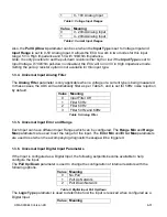
UMAX030440 Version 2B 15-51
Value
Meaning
0
OR, True when Argument 1 or Argument 2 is True
1
AND, True when Argument 1 and Argument 2 are True
2
XOR, True when Argument 1 is not equal to Argument 2
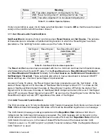
Table 17: Condition Operator Options
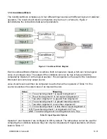
If only one condition is used, it is to make sure that Operator 3 is set to
OR
so that the result is based
solely on the condition which has been chosen.
1.11. Set / Reset Latch Function Block
Set-Reset Block
consists of only 2 control sources:
Reset Source
and
Set Source
. The purpose
of these blocks is to simulate a modified latching function in which the ‘Reset Signal’ has more
precedence. The ‘latching’ function works as per the Table 18 below.
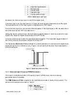
‘Set Signal’ ‘Reset Signal’
‘Set-Reset Block Output’
(Initial State: OFF)
OFF
OFF
Latched State
OFF
ON
OFF
ON
OFF
ON
ON
ON
OFF
Table 18
– Set-Reset Function block operation
The
Reset
and
Set
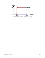
sources have associated with them a minimum and maximum threshold values
which determine the ON and OFF state. For the
Reset Source
are
Reset Minimum Threshold
and
Reset Maximum Threshold
. Similarly, for the
Set Source
are
Set Minimum Threshold
and
Set Maximum Threshold
. These setpoints also allow to have a dead band in between ON/OFF
states and they are in terms of percentage of input selected.
As seen in Table 18 abov
e, the ‘Reset Signal’ has more precedence over the ‘Set Signal’ - if the
state of ‘Reset Signal’ is
ON
, the state of ‘Set-Reset Block Output’ will be
OFF
. To create an
ON
state in ‘Set-Reset Block Output’ the state of ‘Reset Signal’ must be
OFF
while the s
tate of ‘Set
Signal’ is
ON
. In this case, the state of ‘Set-Reset Block Output’ will remain
ON
even if ‘Set Signal’
turns
OFF
as long as ‘Reset Signal’ remains
OFF.
As soon as the ‘Reset Signal’ turns
ON
the ‘Set-
Reset Block Output’ will turn
OFF
regardles
s of the state of ‘Set Signal’.
1.12. CAN Transmit Function Block
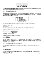
The ECU provides up to 10 fully configurable CAN Transmit messages. Each block can have its own
PGN
. Different transmit messages that share a PGN will be broadcast together as one message.
The CAN transmit message is always enabled and the
Repetition Rate
defines which time in
milliseconds the CAN transmit message is repeated. The CAN message will not transmit on the
J1939 network in case all CAN transmits have the same PGN and the
Repetition Rate
of the first
CAN transmit is set to zero. In the case of shared PGNs the rate of the lowest number CAN
Transmit is used, i.e. if CAN Transmit 1 and CAN Transmit 4 share a PGN, the Repetition Rate of
CAN Transmit 1 is used.


