


EN
4
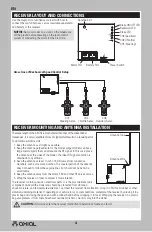
Antenna Exit
Motor Port
Battery Port
Power Switch
Brake ON/OFF LED
Backward LED
Brake LED
CH3 (Auxillary)
CH2 (Throttle)
CH1 (Steering)
RECEIVER MOUNTING AND ANTENNA INSTALLATION
The wave length of the 2.4GHz is much shorter than that of the conventional
frequencies, it is very susceptible to loss of signal which results in a receiving error.
To obtain maximum results:
1. Keep the antenna as straight as possible.
2. Keep the antenna perpendicular to the model. Larger models can have
large metal objects that can attenuate the RF signal. In this case, place
the antenna at the sides of the model. The ideal RF signal condition is
obtained at any attitude.
3. Keep the antenna at least ½ inch (~13mm) away from conductive
materials, such as metal and carbon. The coaxial portion of the antenna
does not need to follow these guidelines, but should not be bent in a
small radius.
4. Keep the antenna away from the motor, ESC and other RF noise sources.
5. Wrap the receiver in foam to protect it from vibration.
The receiver contains precision electronic parts. It is the most delicate radio
component on-board the model and should be protected from vibration,
shock, moisture, and temperature extremes. To protect the receiver from vibration, wrap it in R/C foam rubber or other
vibration-absorbing material. If operating your vehicle in icy or wet conditions, waterproof the receiver by placing it in a
plastic bag and closing the open end with a rubber band before wrapping it in foam. Wrapping the receiver in a plastic
bag also protects it from fuel and exhaust residue which may work its way into the model.
CAUTION:
If moisture enters the receiver, intermittent operation or failure can result.
RECEIVER LAYOUT AND CONNECTIONS
Use the diagrams to familiarize yourself with how to
connect the switch harness, servos (available separately),
and battery to the receiver.
NOTICE:
Set your model on a stand so the wheels are
off the ground before powering on the radio control
system or connecting the motor for the fi rst time.
Glow, Gas or Mechanical Speed Control Setup
CH1
Steering Servo
CH2
Throttle Servo
CH3
Auxillary Servo
Antenna Wire
Antenna Tube


