


6
DRIVE UNIT INSTALLATION
FIG. 4
LEVEL
TRACK
DOOR
FIG. 5
FIG. 3
CENTRE OF DOOR
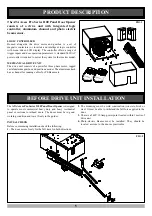
DRIVE UNIT PRE-ASSEMBLY
The drive unit and track assembly are supplied as two separate
parts. The drive sprocket is part of track assembly.
1.
To connect track to drive unit remove front cover.
2.
Disconnect trolley from chain index (
Fig.2
).
3.
Loosen tension on chain. Do not disconnect chain.
4.
Locate sprocket keyway with keyway on Reducer and slide
it in place until face of sprocket boss sits against shoulder
on reducers drive shaft.
Note:
The whole track has to slide with sprocket. It can be
knocked on with a mallet or "helped" with a screw driver.
5.
Once sprocket is in position, lock cap head screw
6.
Secure track to drive unit using M8 x 14 Hex Head screws.
7.
Tighten chain and lock it with lock nuts.
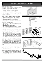
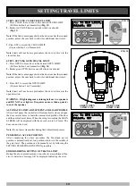
MOUNTING THE DRIVE UNIT
1.
Determine the centre of the door and mark this point on the
wall above (
Fig. 3
).
2.
Raise the door to open position (
Fig. 4
).
3.
Rest the opener on a support above the top edge of the door
to allow for a 25mm gap between the shuttle and the door.
4.
Mark the position of the bracket on the wall above the door
(
Fig. 5
).
5.
Secure bracket in place with loxins or apporpriate fasteners.
6.
Secure the opener to the ceiling above drive unit mounting
holes, with perforated angle or similar (not supplied).
Do not lock screws at this stage.
7.
The door bracket comes in two parts. The top plate is placed
over the bottom plate and uses 4 mounting holes for extra
strength. Mount the door bracket to the centre line of the
door (
Fig. 6
), using M6 or equivalent screws (not supplied)
Alternatively it can be welded on steel doors.
Note:
As various types of doors exist, if in doubt about the
strength of the door, reinforcement may need to be added to the
frame of the frame or panel where necessary. Damage to the
door panel may occur if the bracket is installed incorrectly on a
panel with insufficient strength. The door opener warranty does
not cover damage caused by the opener to the door and/or door
panel.
8.
Assemble bent and straight arm with screws, plain and
spring washer and nuts supplied in accessory pack (
Fig. 7
).
9.
Connect assembled arm to the door bracket and the trolley
by clevis pin and spring clip.
Note:
Shuttle must be in disengage position. Always use both
bent & straight arm. If installing on a door with bad wave
action, lengthening the arm even further will assist the door
operation by reducing the wave action.
FIG. 7
FIG. 6


