


Innovator CHV400BTD ATSC Transmitter
Initial On Site
Turn On Procedure
Technical Manual, Rev. 0
19
Typical Problems, Indications and Causes in CHV200B Tray
Problem
Indication
Cause
No power to
tray
Operate/Standby and Enable LED
indicators and LCD display are Off
AC power cord not connected.
Main AC to System missing.
On/Off switch on back of tray
Off. 10 Amp fuse (F1) blown*.
Power supply (A9) not operating
No Output
Signal
Front Panel Status LED is Amber
and blinking with no events, faults
indicated.
On the 8VSB Modulator S310
MPEG Input Selection Set Up
Screen, the Input is currently set
incorrectly to “from Internal
Source”. Set to “from External
Source”.
Loss of Input
Signal
Loss of Input on Modulator Menu
Loss of input signal.
Loss of
Output
Signal
Amber Operate/Standby LED.
Blinking Red Status LED.
Any Event, Fault, which Mutes
the output. Including Input
Fault, VSWR Cutback, Overdrive,
Overtemperature and
Overvoltage.
Loss of 42V
Power Supply Fault on Power
Supply Menu
Power supply (A10) not
operating
Loss of ±12V
or 5V
Operate/Standby and Enable LED
indicators and LCD display are Off
Power supply (A9) not operating
NOTE:
*A spare 10 Amp fuse is provided in the blank fuse holder under the active
fuse.
If there is an Event (Fault) occurring in the system, the Status LED on the front panel will
flash RED as long as the Event (Fault) is present. In addition, the menu will jump to the
current Event (Fault) on the display and blink the Event (Fault) continuously, if the Jump to
Fault screen is set to Yes. When the Event (Fault) is corrected, the tray will turn the Status
LED to AMBER to indicate that there was a Fault and the menu will still display the Fault but it
will not flash. This gives the user the knowledge that there was an Event (Fault) and what
type of Event (Fault) occurred. Before clearing the fault, check if there were other Events
(Faults) by stepping through the menus. To reset the indication of previous Events (Faults)
the user must push the Enter button with the Event (Fault) Reset Screen displayed. This will
reset all previous Events (Faults).
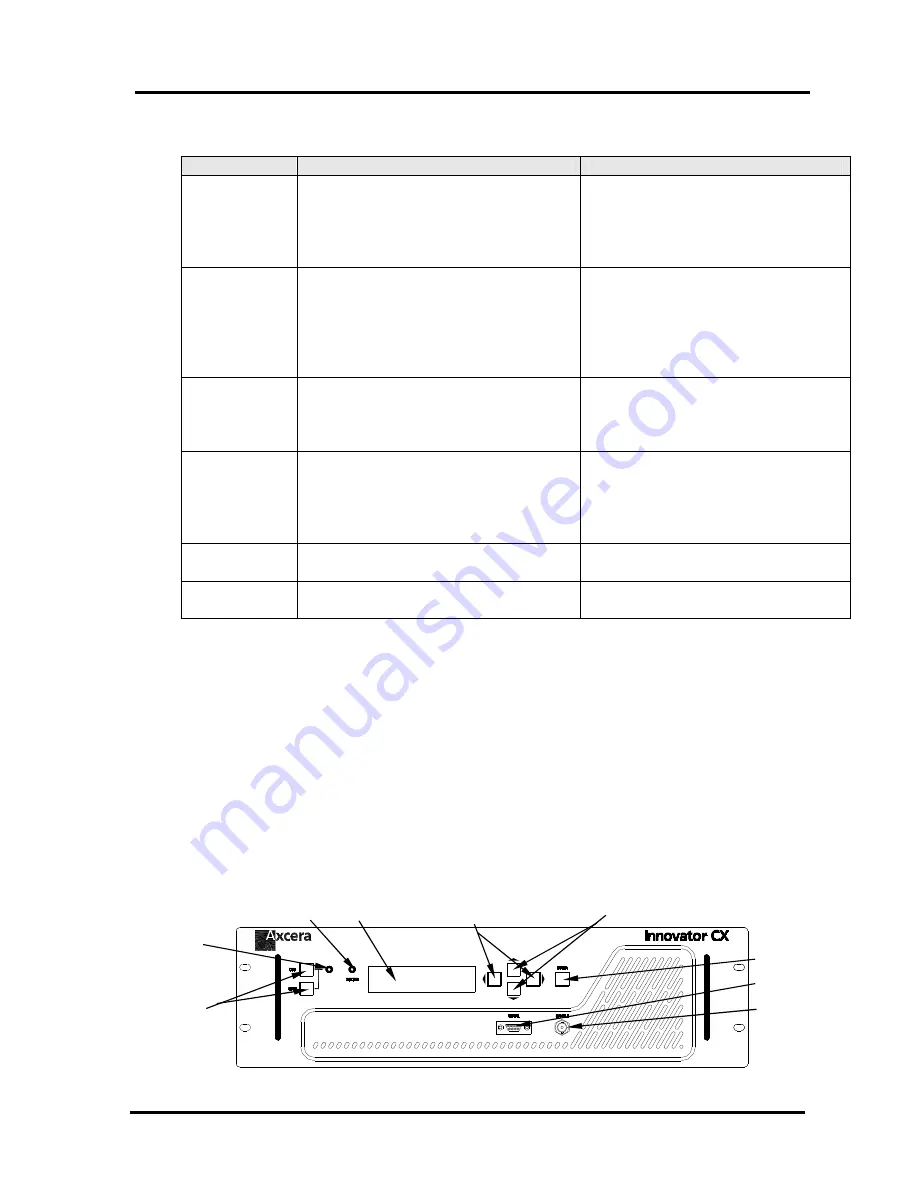
LCD Display and Front Panel LED Indicators
Figure 5: Front View CHV200B and the driver for the CHV400B & higher power systems
Operate/Standby
Buttons
Status LED
Left/Right Buttons
LCD Display
Enter Button
Operate/Standby
LED
Up/Down Buttons
J11 Serial Port
J15 RF Sample
Summary of Contents for CHV400BTD
Page 77: ...APPENDIX A Innovator CHV400BTD ATSC Transmitter System Drawings...
Page 79: ......
Page 80: ...APPENDIX B Innovator CHV20BTD Driver Tray Subassemblies and Boards Drawings...
Page 81: ......
Page 84: ...APPENDIX C Innovator CHV400B Amplifier Tray Subassemblies and Boards Drawings...
Page 85: ......