background image

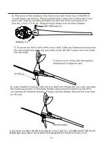
6).Place one of the blades on the hub socket and insert one of the M6-15
 socket head cap screws. Place a plastic disk on the end of the screw, then
place self-locking nut (M6) and tighten it with the 5mm hex key to 8-10 
foot lbs. (10.5-13.5 N.m). Repeat this procedure on all three blades.

M6-16 Screw ( 6 )

M6 Nut ( 6 )

7). Remove the M16 nut from the rotor shaft. Slide the blades assembly onto 
the rotor shaft and place the nut on the shaft. DO NOT press the rotor shaft 
into the body.

Caution: over-torque will damage the 
blades and wind generator.

M16 NUT

8).Insert the 8mm hex key into the rotor shaft and thread the nut on by spinning 
the blades assembly. Holding the blades assembly and tightening the M16 
nut lightly with the 8mm hex key. Finally, spin the blades slowly to be sure they 
turn freely.

8mm Hex Key

CAUTION: DO NOT SCREW M16 NUT TOO TIGHTLY, OTHERWISE THE FACE 
BEARING WILL BE STUCK AND THE BLADES ROTATE DIFFICULTLY!

13

Summary of Contents for AWS400W

Page 1: ...Please read and understand this manual completely before operating the machine Serial number AUSTRALIAN WIND AND SOLAR www australianwindandsolar com AWS400W Wind Turbine Ver 2 3 Revised 6 5 2020...

Page 2: ...2...

Page 3: ...R WIRING 6 3 INSTALLATION OPERATION 6 4 ATTACHING TO POLE 6 5 STEP BY STEP INSTRUCTION 7 WARRANTY POLICY 7 1 ELEVATION 8 WARRANTY 4 4 4 4 5 6 6 7 8 9 10 11 11 12 15 15 16 AWS Marine grade 400 Watt Win...

Page 4: ...high surge electrical dangers The internal electronics of the AWS Wind Turbine prevents open circuit voltages from rising above 20 volts for 12 volt systems Please note that the inherent personal dan...

Page 5: ...the turbine rotor will require approximately 60 100 hours of operation in normal wind speeds approximately 18 20 mph 8 9 m s before they are running at peak efficiency During this break in period the...

Page 6: ...t shrink not included Wire strippers not included Wire crimpers not included NOTE Do not connect to the battery Precheck Spin rotor shaft slowly with your fingers while at the same time connecting and...

Page 7: ...bulence Smooth laminar airflow 2H 20H Turbulent airflow 2H H Turbulent airflow created by obstructions Ad P Gipe 93 Therefore as a general rule the Wind Generator should be mounted twice as high as an...

Page 8: ...cost and effort of the installation This Wind Generator is designed to use steel pipe 1 875 inch 48mm outside diameter equivalent to 1 inch SCH 40 pipe which can be used in some tower applications If...

Page 9: ...perature exceeded 90C or temperature sensor damage Rotor rotating at 0 1000rpm Normal mode Flashing green Charging wind speed to 10m s to 14m s Rotor rotating at 1000rpm to 1300rpm System returns to n...

Page 10: ...ily damaged internal controller in wind condition the warranty will not covered The power meter box main function is display and break the wind turbine the MPPT controller in the wind turbine body Pow...

Page 11: ...CAREFULLY NOTE DO NOT install the blade assembly until the body is mounted on the tower CAUTION ALL BATTERIES MUST DISCONNECTED THROUGHOUT THE INSTALLATION PROCESS CAUTION DO NOT INSTALL THE WIND GEN...

Page 12: ...generator by the pipe 3 Connect the Wind Generator to the wires and insulate the connections using either heat shrink tubing or a quality electrical tape 4 Once the yaw shaft is on the tower firmly t...

Page 13: ...blades assembly onto the rotor shaft and place the nut on the shaft DO NOT press the rotor shaft into the body Caution over torque will damage the blades and wind generator M16 NUT 8 Insert the 8mm he...

Page 14: ...m should be connected to a ground This is usually done by connecting a wire from the negative battery terminal to a nearby ground rod Wires with the same ratings as the positive and negative wires mus...

Page 15: ...8 000 9 000ft 9 000 10 000ft 150 300m 300 600m 600 900m 900 1 200m 1 200 1 500m 1 500 1 800m 1 800 2 100m 2 100 2 400m 2 400 2 700m 2 700 3 000m 97 94 91 88 85 82 79 76 73 70 7 1 ELEVATION An importa...

Page 16: ...r com Warranty Registration Card Warranty Service Card Model Number Installation Location Model Number Application Procedure Problem Description Total Work Period Other Requirements Send at least thre...

Reviews: