background image

- Page -  6 -

ADVANCED WATER ENGINEERING, INC.

Indian Harbour Beach, FL
www.advancedwater.com

7.

CONNECTING THE COMPONENTS

Each component on the R.O. filter assembly connection is made by following the Fast-Tite®

assembly instructions on page 6-7.

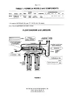
A. Connect yellow tubing from raw water supply valve to the inlet pre-filter. (Refer to Figure 1 &

2).

B. Connect 

BLUE

 tubing to the product water tee on post filter to faucet. (Refer to Figure 2).

C. Connect 

1/4” BLACK

 tubing to faucet air gap and 

3/8” RED

 tubing from faucet air gap to

drain.

8. START-UP PROCEDURE

A. Turn on the feed water valve and watch 

carefully 

for leaks.

B.Turn on the storage tank valve and check for leaks.
C.

Correct any leakage problems as necessary.

CAUTION: Do not use the first gallon of water 

from 

faucet or from the icemaker. This first

gallon 

of 

water flushes the entire system, removing any preservatives used during shipping

and storage, 

preparing 

it to produce R.O. water.

SECTION 3

Service Instructions

Pre-Filter Replacement

1 Turn 

off water valve and storage tank valve.

2. Open faucet to release pressure.

3. Unscrew the white pre-filter housing.

4. Replace pre-filter. (Replacement part number found on filter housing.)

5. Clean housing, if necessary, with a mild chlorine solution. Rinse away all chlorine before

reassembly.

6. Before reinstalling pre-filter, make certain 0-ring is seated in housing.

Summary of Contents for MODELS II

Page 1: ...AWE LINE PRESSURE REVERSE AWE LINE PRESSURE REVERSE OSMOSIS DRINKING WATER SYSTEMS MODELS II III ...

Page 2: ...fines carbon cartridge containing approximately 4 million square feet of surface area This carbon is capable of treating approximately 6 000 gallons of water entering the filter with a free chlorine residual of 2 5 ppm The carbon filter is required to protect thin film membranes from free chlorine Change the carbon filter every year or sooner depending on your water supply and dealer recommendatio...

Page 3: ... S and temperature A 1 4 valve is provided to isolate the storage tank from the system SERVICE CONNECTIONS The sink top faucet is dedicated to dispense water from the storage tank It can rotate a full 360 degrees and can dispense water continuously or intermittently The faucet is equipped with an air gap feature to prevent a cross connection between the potable water supply waste water drain The T...

Page 4: ...so be in a location that allows ready access to the mounting hardware from under the sink 2 INSTALLATION OF T VALVE ASSEMBLY A Turn off the Cold Water Supply B The i Link Ball valve Assembly may be used to make connection to3 8 plastic copper or corrugated tubing To install carefully cut the tubing with hacksaw or tubing cutter Usually a single cut is all that is needed Remove nuts and rubber grom...

Page 5: ...umbing C Hand tighten both screws evenly using a Philips screw driver 5 MOUNTING THE FILTER ASSEMBLY The Filter Assembly can either be mounted on the cabinet sidewall so that the filters are up off the cabinet floor or the assembly can be set on the cabinet floor Care must be taken to assure the sidewall is sufficiently strong to support the 15 pound weight of the operating assembly A Hold the Fil...

Page 6: ...and watch carefully for leaks B Turn on the storage tank valve and check for leaks C Correct any leakage problems as necessary CAUTION Do not use the first gallon of water from faucet or from the icemaker This first gallon of water flushes the entire system removing any preservatives used during shipping and storage preparing it to produce R O water SECTION 3 Service Instructions Pre Filter Replac...

Page 7: ...g in you will feel the membrane stop With a little more pressure and turning action the membrane will move in another 1 4 3 8 of an inch When this occurs the 0 Ring has been properly seated 7 Inspect housing 0 Ring for damage If damaged replace Wet and install the 0 Ring on the housing Replace end cap and tubing 8 Follow Start up procedure for restart unit Post Filter Replacement 1 Follow steps 1 ...

Page 8: ...lement must remain wet Put membrane element in a plastic bag 4 Fill empty pre filter housing with sanitizing solution and turn on raw water After holding tank is full let system stand idle for approximately 30 minutes 5 Turn off water 6 Drain holding tank via the R 0 faucet 7 Reinstall new pre filters and membrane element 8 Replace post filter 9 Disconnect line to faucet and ice maker and put appr...

Page 9: ...at covers a base metal so extreme care should be taken to keep from chipping this surface There are several methods that allow ceramic sinks to be drilled safely and easily One that we suggest is 1 Locate faucet placement and tape off the area with masking tape 2 Using a drill at slow speeds drill through the porcelain using 1 4 carbide tipped drill Note The bits dull in a very short period of tim...

Page 10: ...n the bit is about to penetrate the tile C Drilling Stainless Steel Sinks 1 Determine faucet locations and center punch the stainless for the drill bit 2 After drilling a pilot hole using a high speed carbide bit increase the bit size until you have drilled a hole at least 1 1 4 in diameter Step by step assembly STEP 1 Read all instructions before beginning installation Verify that all parts have ...

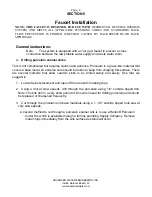
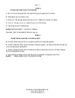
Page 11: ...E Lower faucet into mounting hole NOTE FOR PROPER FIT CUT POLY TUBING SQUARE NOT AT AN ANGLE Refer to Sec 6 STEP 4 Install Faucet assembly in mounting hole A Position faucet through hole in countertop with front in desired position B Position Retainer Plate Spacer Washer and Star washer over base screw and thread hex nut onto base screw and tighten C Place Compression Hex Nut Compression Sleeve an...

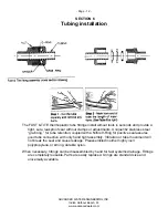
Page 12: ...less steel grab ring for tube retention coupled with a Nitrile 0 Ring for positive seal assures good tube connection with only hand tight assembly Vibration or tube movement will not break the seal and cause leakage Preassembled in either highly inert polypropylene or strong durable nylon When necessary fittings can be disassembled by hand for fast systems drainage Fittings are completely reusable...

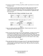
Page 13: ...e Support InsertionLength with Tube Support 1 40 D 9 16 5 8 3 80 D 3 4 13 16 Step 3 Loosen nut on fitting until three threads are visible Fittings for glass tubes must be disassembled and the grab ring removed Step4 Moisten end of the tube with water Push the tubes STRAIGHT in to fittings until it bottoms on the fittings shoulders Tighten nut by hand Additional tightening should not be necessary b...

Page 14: ... Page 14 ADVANCED WATER ENGINEERING INC Indian Harbour Beach FL www advancedwater com ...

Page 15: ... Page 15 ADVANCED WATER ENGINEERING INC Indian Harbour Beach FL www advancedwater com ...

Reviews: