24
3.
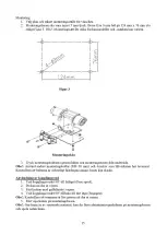
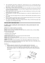
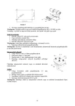
Insert the mounting bolts through the holes and the mounting plate from the bottom up.
Note:
Use only the mounting bolts (M8 ×30MM) and washers supplied by the manufacturer.
Be sure the bolts are properly tightened, otherwise the base can be damaged.
Clutch Operation
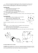
1.
Turn the clutch 90° to the Free spool position.
2.
Let the nylon rope from the drum.
3.
Connect the clevis hook on the nylon rope.
4.
Turn the clutch 90° back to the Engaged position.
Note:
Make sure that the drum is engaged by pulling the nylon rope.
5.
Fix the fairlead on the mounting plate.
Note:
If the rope is synthetic, you can fix the aluminium fairlead on the mounting plate and then
reel the rope.
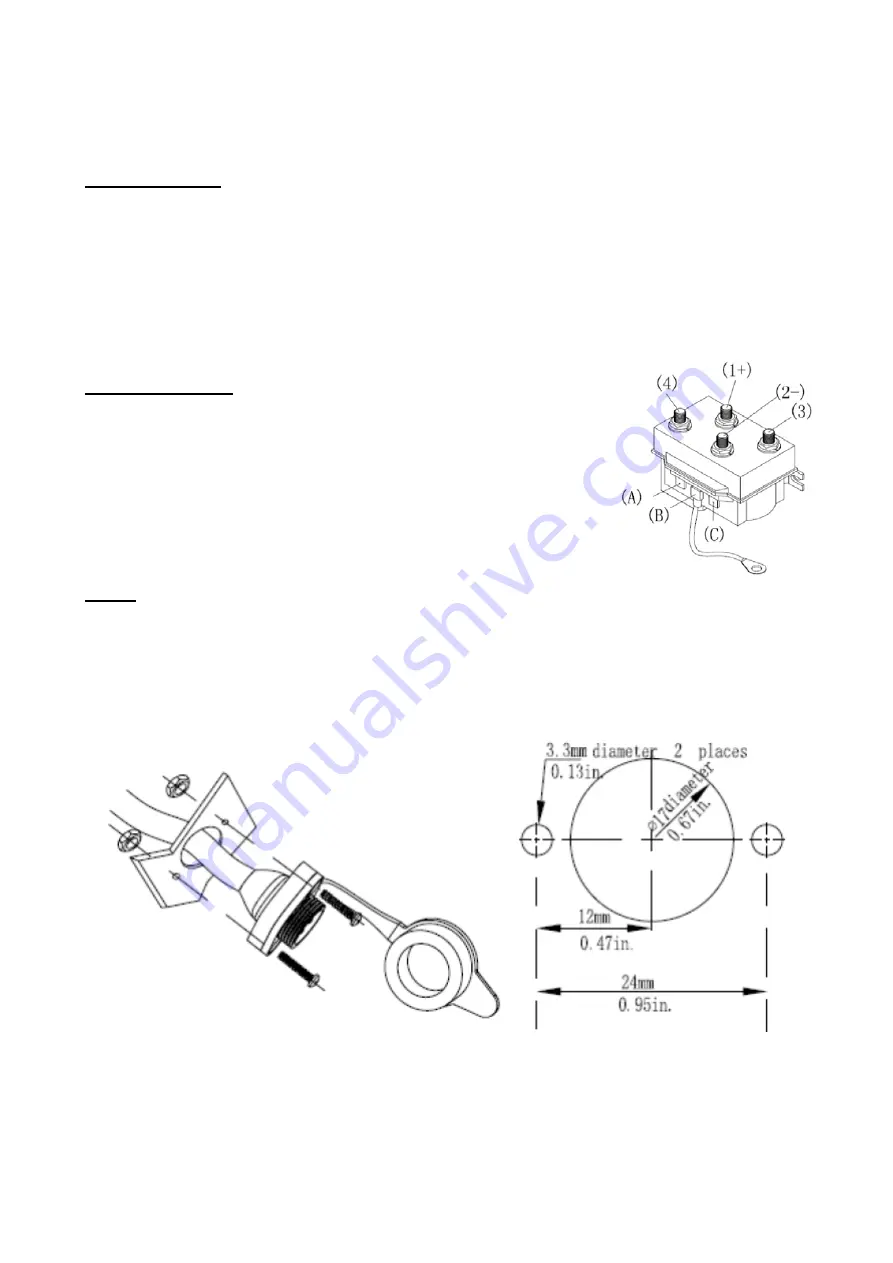
Integrated solenoid
1.
C
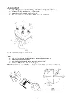
hoose a suitable and safe mounting location for the ISM.
2.
The thickness of the location must be 2-5 mm.
3.
Drill two 6 mm holes with the distance 67 mm.
4.
Fix then the integrated solenoid with the bolts (M5X12)
properly.
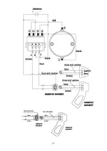
Connect the integrated solenoid as shown in the electric diagram
below.
Socket
1.
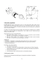
Choose a 2–5 mm mounting location for installing the chrome-plated socket.
2.
Drill the holes as shown in the figure below.
3.
Remove the bolt on the socket and push the wire through the biggest hole.
4.
Use a M3×16 bolt to fasten the socket.
Note:
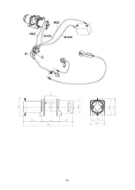
Connect the socket and integrated solenoid as shown in the figure in the end of this manual.
WINCH WIRING INSTALLATION
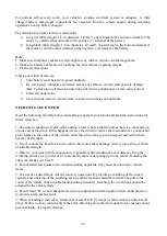
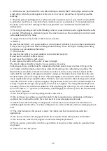
CAUTION:
When attaching wires to the motor or solenoid terminals, hold the inner nut with a
wrench while tightening the outer nut with a second wrench. Do not allow the terminals to rotate in
their housings. Rotation may cause internal wire damage or part misalignment.

