


Ý
ØßÐÌÛÎ
î
| Installing the RG300
Cable Connections
22
îò
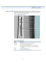
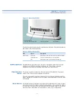
Observe the Indicator LEDs. When you power on the RG300, verify that
the Power LED turns on and that the other LED indicators start
functioning as described under
RG300 Hardware Description
on
page 15
.
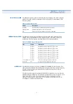
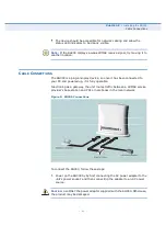
íò
Connect Category 5 or better Ethernet cables from the RG300
s LAN
ports to the network ports of your PCs. Alternatively, you can connect
the LAN port to an Ethernet switch or other device. Make sure the
length of each cable does not exceed 100 meters (328 ft).
If a PC is powered on, the RJ-45 LAN port LED on the RG300 will turn
on to indicate a valid link.
ìò
(Optional) Connect a standard (analog) telephone set to one of the
RG300
s VoIP ports using standard telephone cable with RJ-11 plugs.
The RG300 enables VoIP calls to be made through the unit using a
standard (analog) telephone set connected to the VoIP port, or from
PCs or other network devices connected to the LAN ports. Standard
Session Initiation Protocol (SIP) technology is used to make VoIP calls.
You must access the web interface and configure settings for your SIP
service provider before being able to make VoIP calls.
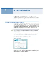
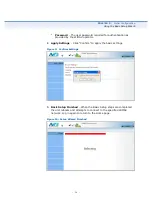
ëò
Use your PC
s web browser to access the unit
s management interface
and run the Setup Wizard to make any configuration changes. For more
information, see Chapter 3,
Initial Configuration
.