background image

3

461306964_004   01/2014

Before this appliance left the factory it was tested and fine-tuned by specialised expert personnel in order to 

guarantee its best functioning results.

Any subsequent repairs or adjustments that may be necessary must be done with the maximum of care 

and attention by qualified personnel.

For this reason we recommend you always contact our Service Centre specifying the brand, the model, its serial 

number and type of problem you are facing with it. All data related to your appliance are printed on the data label 

affixed behind the appliance as well as on its original packaging.

A duplicate data label is contained in this booklet also. Please attach this label on the handbook or to an 

accessible surface near by the appliance for easy reference.

This information enables the technical assistant to come and visit you with the correct spares and guarantee a 

prompt and suitable service.

You will only find original spare parts at our Service Centre and authorised dealers.

ASSISTANCE AND SPARE PARTS

CONTENTS

ASSISTANCE AND SPARE PARTS

3

IMPORTANT NOTES AND PRECAUTIONS FOR USE

4-6

DESCRIPTION OF THE APPLIANCE

7-9

INSTRUCTIONS FOR THE USER 

10-19

TROUBLESHOOTING

20

TECHNICAL FEATURES

20-21

INSTRUCTIONS FOR THE USER

22-32

Summary of Contents for A9061BL

Page 1: ...461306964_004 01 2014 INSTRUCTIONS AND ADVICE FOR INSTALLING USING AND SERVICING OF COOKERS MODEL A9061XT A9061BL A9061C ...

Page 2: ... waste recycling centre specifically for electric and electronic equipment or returned to the retailer at the moment of purchase of a new equivalent appliance The user is responsible for delivering the appliance to the appropriate collection centre at the end of its useful life Failure to do so may result in a fine as provided for by laws governing waste disposal Differential collection of waste p...

Page 3: ...the data label affixed behind the appliance as well as on its original packaging A duplicate data label is contained in this booklet also Please attach this label on the handbook or to an accessible surface near by the appliance for easy reference This information enables the technical assistant to come and visit you with the correct spares and guarantee a prompt and suitable service You will only...

Page 4: ...er and as such dangerous The manufacturer cannot be held responsible for any damage to persons or property resulting from an incorrect installation maintenance or use of the appliance Once the packaging has been removed from the outer surfaces and the various inner parts thoroughly check that the appliance is in perfect condition If you have any doubts do not use the appliance and call in an autho...

Page 5: ...ore cooking for the first time ensure the oven is empty and its door closed heat the oven at maximum temperature for two hours This will allow the protective coating on the interior of the oven to be burnt off and dissipate the associated smells Ensure adequate ventilation in the kitchen whilst burning off and don t be alarmed by a little bit of smoke during this process When you insert the oven s...

Page 6: ...ing the lid Not suitable for installation or operation with aftermarket lids or covers Avoid using the oven as a larder or as a saucepan cupboard when you are not using it for cooking if the oven is turned on accidentally it could cause damage and accidents If you are using an electrical socket near the appliance make sure that the cables are not touching the cooker and are far enough away from al...

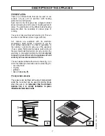
Page 7: ... without supervision In order to guarantee to the customer a good and safe use of the appliance it has a safety thermostat that starts working should the main thermostat malfunction In such an event the electricity is interrupted temporarily do not attempt to repair it yourself but turn the appliance off and contact your nearest Assistance Centre The oven walls are fitted with various runners fig ...

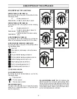
Page 8: ...ch stays on for all functions Fan on Top and bottom heating elements on Top and bottom heating elements and fan on Bottom heating element and fan on Rear heating element and fan on Grill spit heating element on Grill heating element and fan on only certain versions GAS BURNER KNOB H By turning the knob counterclockwise we find the following symbols 0 closed position Full on position Reduced rate p...

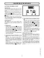
Page 9: ...s off symbol A and dur flash At the end of the set time the buzzer will start and the symbol A flashes To turn off the buzzer press MODE button Now the oven is off Keep pressed for some seconds simultaneously and buttons or just MODE button and the symbol is illuminated 3 Fully automatic program with Duration and End time Select with and buttons the duration and the end time The time of the day tu...

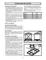
Page 10: ...he selected burner and repeat the above steps OPTIMUM USE OF THE BURNERS In order to achieve maximum efficiency with minimum gas consumption it is useful to remember Do not use large burners with pans of small diameter in order to avoid flames spreading wider than pans consult the following table and always use pans with lids fig 3 Avoid using over sized pans that may radiate excessive heat and ca...

Page 11: ...S FOR USING CERAMIC GLASS HOBS Ceramic glass is a natural product and like any other material in ceramic can have an uneven surface You might even see some bubbles inside the ceramic glass itself these will not influence cooking or the lifetime of the hob Illumination of the single cooking zones might differ This depends on the technical characteristics of the heating elements This has absolutely ...

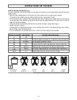
Page 12: ...t flat will make cooking times longer Always put a lid on the pan If cooking time is longer than 40 minutes you can switch the plate off 5 to 10 minutes before the end of cooking time and make use of the residual heat For your information only the table gives hints on how to use the cooking zones and plates Position of knobs Heat intensity Possible cooking processes 0 Off 1 2 Low To dissolve butte...

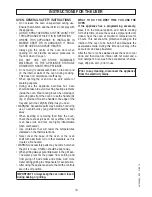
Page 13: ...low onto the oven base oils and fats are highly inflammable when overheated Use containers that will resist the temperatures indicated on the thermostat knob Never cover the base of the oven or the oven shelf with aluminium foil or other materials as this creates a fire hazard WARNING Accessible parts may become hot when the grill is in use Children should be kept away When grilling always put a l...

Page 14: ...unctionwillactivate the bottom heating unit and its heat is distributed by the fan This function is particularly recommended to defrost and warm up ready made meals FAN REAR HEATING COMBINED COOKING Turn the selector knob to the symbol and set the thermostat to the desired temperature then place your food the oven If oven needs pre heating wait till the thermostat yellow led turns off before placi...

Page 15: ... or bread crumbs If the biscuits will not come away from the baking tray put the tray back in the oven for a while and lift the biscuits up before they cool The next time use a sheet of baking parchment to prevent this happening again Meat If when cooking meat the time needed is more than 40 minutes turn the oven off 10 minutes before the end of cooking time to exploit the residual heat energy sav...

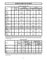
Page 16: ...190 190 200 190 200 15 20 40 45 CAKES Angel cake Fruit cake Chocolate cake 0 8 0 8 0 8 2 2 2 190 200 200 52 65 45 170 190 190 200 190 200 45 65 45 The values given in the tables temperatures and cooking times are approximate and may vary according to each person s cooking habits This table gives cooking times on only one shelf If you are cooking with a fan oven and you are using more than one shel...

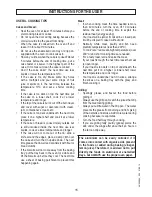
Page 17: ... tap is difficult to open or close do not force it but call for technical assistance urgently CERAMIC GLASS HOB It is very important to clean the top each time it is used and while the glass is still warm drying it with a soft cloth Do not use metal pads abrasive powders or corrosive spray products for cleaning Depending on the degree of dirt we recommend For slight stains a damp sponge is enough ...

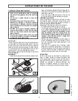
Page 18: ...ILS fig 11 For an effective cleaning of the oven side guide rails these can be extracted unscrewing knurled nuts G To fit the rails back in their place first insert rear pins A in holes B and then secure them with the knurled nuts G INSTRUCTIONS FOR THE USER SELF CLEANING PANELS Oven walls are protected by panels coated with a grease proof microporous enamel that absorbs and eliminates splattering...

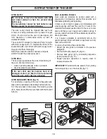
Page 19: ...the aid of specialized personnel Just open the oven door and remove the support securing the glass fig 15 ATTENTION This operation can be done also with the door fitted on appliance but in this way pay attention that when the glass is pull upwards the force of the hinges can close the door roughly LOCK AT LEAST ONE HINGE fig 14 REPLACING THE OVEN LAMP fig 16 Ensure the appliance is switched off be...

Page 20: ...ectric thermostat warning light does not switch on during use Turn the thermostat round to a hotter temperature Turn the selector round to a different function The oven light does not switch on Make sure the lamp is firmly screwed in place Buy a lamp for high temperatures at one of our Service Centre and fit it following the instructions given in paragraph REPLACING THE OVEN LAMP Warning Servicing...

Page 21: ...ting element Fan of the rear heating element Oven lamp 2100 W 2000 2200 W 3000 W 25 29 W 40 W T 300 CABLE TYPES Cooker type Cable type Single phase power 230 V ac Three phase power 230 V ac 3 Two phase power 400 V ac 2N Three phase power 400 V ac 3N cross section cross section cross section cross section All electric cooker H05 RR F 13mm Ø 14mm 3 x 6 mm2 4 x 4 mm2 4 x 4 mm2 5 x 2 5 mm2 Combined co...

Page 22: ... given below for ventilation and aeration UNPACKING YOUR COOKER Oncethewrappinghasbeenremovedfromtheouter surfaces and the various inner parts thoroughly check that the appliance is in perfect condition If you have any doubts do not use the appliance and call in a qualified person Some parts mounted on the appliance are protected by a plastic film This protection must be removed beforeusingtheappl...

Page 23: ... The cookers which are equipped with this accessory leave of the factory with this particular inserted inside the packing In order to install the backguard it is necessary to loosen the screws positioned on the back of the hob and then to fix the backgaurd as indicated in figure 22 Spacers only certain versions positioned behind the rear panel to keep the appliance at the minimum required distance...

Page 24: ...ng forwards in the event of children standing on the oven door or where users put extreme weight on the door when in open position two chains MUST BE fixed to the back of the oven which should at all times be secured to the threaded pins The threaded pins should be secured to the wall at the back of the cooker Assembly instructions Secure threaded pins into wall immediately behind and to the left ...

Page 25: ...ied directly from a gas cylinder the appliance fed by a pressure regulator in accordance with the standard must be connected with a copper pipe in accordance with the standard whose joints must be made using sealed fittings in accordance with the standard with a flexible stainless steel seamless pipe in accordance with the standard with a maximum 2 metre extension and seals in accordance with the ...

Page 26: ...zed plug suitable for the load which is indicated on the data label Connect the wires making sure they correspond as shown below and remember that the earth wire must be longer than the phase wires letter L phase brown wire letter N neutral blue wire symbol earth green yellow wire The power cable must be laid so that no parts of it ever reach a temperature of 75 C For connecting do not use adapter...

Page 27: ...V until the flame of the burner is conveniently regulated to the Low position Check that the flame does not go out when the knob is sharply switched from the Full on to Reduced rate positions ATTENTION This operation can be carried out also with the front panel fitted but if the technician finds some difficulties to reach the adjustment screw remove the front panel unscrewing the fixing screws whi...

Page 28: ...ng screws Vs fig 27 which lock the hob at the supports S Pull out the knobs Unscrew the nuts D of the gas aluminium pipes and pull out the thermocouple quick connectors F fig 28 Unscrew the screws Vt fig 28 which lock the crosspieces l Unscrew the screws Vb fig 28 which unite the the bridles of the taps to the front frame Make to slip the ramp toward the back part and unscrew the screws Vb fig 29 ...

Page 29: ... see the cross section on table on page 19 always keep the earth wire longer than the phase wires and in addition follow all the instructions given in the ELECTRICAL CONNECTION paragraph To change the lamp holder P fig 30 remove the side panels and then use a screwdriver to push the two locking tabs and remove the lamp holder from the inside of the oven To change the hob electrical heating element...

Page 30: ...30 ...

Page 31: ...31 461306964_004 01 2014 ...

Page 32: ...SPACE FOR DATA LABEL ...

Reviews: