ELECTRICAL SPECIFICATIONS
A. Operating Power (Vin)
1. Volts ............................ 5-24 VDC in
2. Current ....................... 100mA, each output, plus cable load
B. Output Format
1. 2O/ & Comp ................ A,A–, B,B– (differential line driver)
2. Marker: ....................... 1/Rev Z, Z–
C. Signal Type ..................... Incremental, Square Wave, 50 +/-10%
...................................
Duty Cycle.
D. Direction Sensing ........... O/ A leads O/ B for CW rotation as viewed
...................................
from the back of the tach
looking at the
...................................
non-drive end of
the motor.
E. Transition Sep. ............... 15% minimum
F. Frequency Range ........... 0 to 165,000 Hz
G. PPR ................................ 8-5000
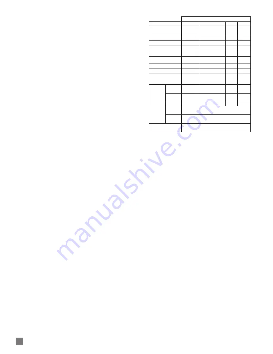
H. Line Driver Specs: .......... See table
I. Connectors: .................... See connector options on page 1
MECHANICAL
A. Shaft Inertia .................... 1.59 lb-in-sec
2
B. Acceleration .................... 5000 RPM/Sec. Max.
C. Speed: ............................ 5000 RPM Max (also see overspeed)
D. Weight: ........................... 10-12 lbs [4.5-5.5kg]
E. Vibration ......................... 20 Gs, 5-2000 Hz (any orientation)
F. Shock ............................. 100 Gs, any orientation
G. Shaft Load:.....................
ENVIRONMENTAL
Solid cast aluminum stator and rotor
Fully potted electronics, protected against oil and water spray
Operating Temperature:.......-40°C to +100°C.
MECHANICAL OVERSPEED SWITCH OPTION
A. Shaft Inertia .................... +0.0018 lb-in-sec
2
B. Acceleration .................... 3600 RPM/Sec. Max.
C. Speed: ............................ 1.25 x Overspeed set point Max.
Minimum trip speed: 700 RPM
Maximum trip: 3600 RPM
Ac/- 4% of trip point
Hysteresis: 40% of trip point
D. Weight: ............................ +2.55 lbs [+1.16kg]
E. Vibration: ........................ 20 Gs, 5-2000 Hz (radial only)
F. Shock: ............................ 100Gs, any orientation
G. Electrical Contact (NO/NC Contact)
1. ................................... 6A/230VAC
2. .................................... 3A/380VAC
3. .....................................1A/125VDC
H. Operating Temperature:......-40°C to +100°C.
LINE DRIVER OPTIONS
Electrical Specifications
6
8
9
Units
Input Voltage
5-24
5-24
5-24
VDC
Nom Output Voltage
5-24
5-15
5
VDC
Line Driver
7272
4125
7272
Output Resistance Typ
13
3
13
ohms
Maximum Peak Current
1500
3000
1500
mA
Maximum Average
Current
120
350
120
mA
Voh Typ
V
IN
-1
V
IN
-1, max 15V out
V
IN
-1
VDC
Vol Typ
0.5
0.4
0.5
VDC
Cable Drive Capacity
1000’ @ 5V
500’ @ 12V
200’ @ 24V
1000’
1000’
feet
Protection
Reverse
Voltage
yes
yes
yes
Short
Circuit
yes
yes
yes
Transient
yes
yes
yes
Alarm
+V(out)
Output voltage equal to input voltage.
Alarm*
Open collector, normally off, goes low on alarm,
sink 100mA max, 50VDC max
Marker
One per revolution. Pulse width
approximately 1/128 of a revolution
2
ADAPTIVE ELECTRONICS
A perfect duty cycle consists of a waveform whose “high” and “low”
conditions are of the same duration (50%/50%). It is possible over
time for the duty cycle and edge separation to change due to com-
ponent drift, temperature changes, or mechanical wear. The Adap-
tive Electronics extend the life of the AV45 by constantly monitor-
ing and correcting duty cycle and edge separation over time.
FAULT-CHECK
If the Adaptive Electronics reach their adjustment limit, the LED will
turn red and Fault-Check alarm will notify the drive and operator
of an impending failure. This output can occur before a failure,
allowing steps to be taken to replace the unit before it causes un-
scheduled downtime. Fault-Check annunciation is available as an
“alarm” output through the connector.
SAFETY
The AV45 is not considered as a safety device and is not suitable
for connection into a safety system. The mechanical overspeed
switch (option 6xx) is suitable for connection into safety systems.
CAUTION
Do not disassemble mechanical overspeed option.
Doing so may modify the overspeed set point or
cause the switch to malfunction. If the factory seals
are not intact on the overspeed switch, do not use
it--return to the factory for service and calibration.
WARNING
Installation should be performed only by quali-
fied personnel. Safety precautions must be taken
to ensure machinery cannot rotate and all sourc-
es of power are removed during installation.


