


CAMERA PARAMETERS
This camera series has its own configuration menu, and either of the two methods below is available to
access the menu based on the camera model you have.
Note:
The methods below are available only when the camera is used with our brand’s HD CCTV
DVR.
Method 1
On the DVR live view, click the channel which connects this camera to display in the full screen mode,
and select
.
Method 2
On the DVR live view, right click to show the DVR main menu, and select
ADVANCED CONFIG
DCCS
. Then, select the channel which connects this camera, and click SETUP to enter the menu of
camera parameters.
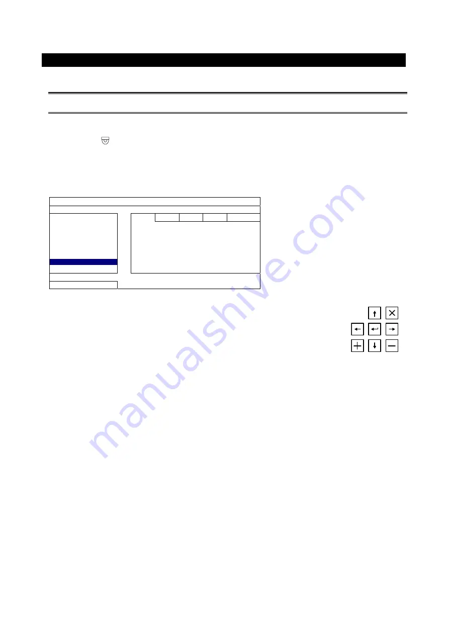
ADVANCED CONFIG
CAMERA
CH1 CH2 CH3 CH4
DETECTION
MENU SETUP
ALERT
NETWORK
DISPLAY
RECORD
F.W. 1015
DCCS
DEVICE AVTXXX
NOTIFY
CONNECTION OK
EXIT
When the camera menu is entered, you’ll see the keys on the bottom right corner to
move between and change those configurations.
Move between selections.
Change settings.
Call the camera parameters menu or enter the currently-selected item.
X
Quit the camera parameters mode.


