background image


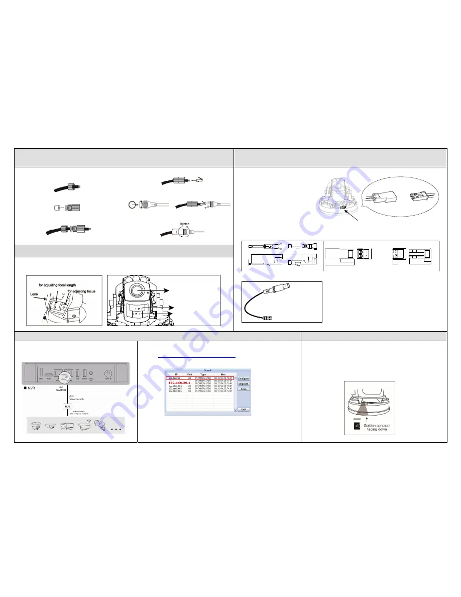
 Waterproof Accessories Installation   

(Selected Model Only) 

 Preview the Viewing Angle with a BNC Monitor 

    (Selected Model Only) 

Step 1: Pass the network cable without connector through the 

plastic tube cover as the right illustration. 


Step 2: Put the waterproof seal into the plastic tube. 


Step 3: Pass the network cable through the plastic tube and 

screw it tightly. 


Step 4: Install a connector to the network cable. 


Step 5: Put the O-Ring on the plastic tube as the left 

illustration and connect the network cable with plastic 
tube to the RJ45 waterproof connector of camera,   


Step 6: Screw them tightly to prevent water seepage. 


 Focusing the Camera


If you need to adjust the focus, the picture shows you how to adjust. 

Type A                                                                                  Type B 


F

T

W

N

for adjusting focal length

for adjusting focus

lens


This camera support composite output for you to   
preview the viewing angle if it’s correct or not 
while installing camera. You need to open the 
plate to find the receptacle housing of RCY 
connector located next to the micro SD card 
slot as the right illustration.   

Please follow the specifications as below to 
purchase the suitable plug. 


Specification of contact 


Specification of housing 

0.

64

15.8

1.7 2

1.

7

1.

7

11

1.8 2

1.

1

9.5

2.5 2.9 6.7

2.5

3.2

5.3 6.3

13

4.3

19

Receptacle housing (for pin contact)

Plug (for socket contact)


Overview of optional plug cable 

Connect to a RCA cable


 Camera Configuration   


 Inserting MicroSD Card 

For advanced configuration of your camera, please be sure you have 

connected your camera to NVR as shown below: 


Step1: Connect PC to the HUB connected to your camera(s) with RJ45 network cable. 
Step2: Search available devices with “IPScan.exe”; to download “IPScan.exe”, please visit 

www.surveillance-download.com/user/IPscan.zip


Step3: After searching, set your PC in the same network segment as the specific camera 

you want to access, such as “192.168.30.xxx” (xxx could be 0~255) in our example 


Step4: Note down the IP address and port number of the camera you want to access, such 

as “192.168.30.1” and “88” in our example. 

Step5: Open Internet Explorer on the PC, and enter the IP address and port number in 

the URL column to access the camera. The format is http://ipaddress:portnum, 
such as 

http://192.168.30.1:88

 in our example. 

The data originally saved in the microSD card (if any) will be removed after 

inserting it to the camera.   

The camera doesn’t support hot-swapping. Please insert or remove the microSD 

card with power disconnected. 

Please follow the directions in the below graphic to insert MicroSD card properly: 


Receptacle housing

Plug (Optional)

Summary of Contents for avm420s

Page 1: ...nce of 20Ω such as CAT 5e or CAT 6 cables to conform to the standard of IEEE802 3af For Type 1 only Installation Type 1 Type 2 Step1 Remove the camera base as shown in Figure 1 and disassemble the camera to four parts as shown in Figure 2 Rotate anti clockwise Remove Camera lens Part 1 Part 2 Base Figure 1 Figure 2 Step2 Locate where you want to install this camera wall or ceiling and drill holes ...

Page 2: ... properly Note It s recommended to use a pair of tweezers for inserting removing Micro SD card Camera Configuration For advanced configuration of your camera please be sure you have connected your camera to NVR as shown in HD System Connection Note It s recommended to connect the camera to the same brand s NVR to get the best performance To use the camera individually please refer to the camera s ...

Page 3: ...eters Step 4 Fix the camera to the ceiling or wall with the supplied screws Step 5 Connect your camera to power Step 6 Pan tilt and rotate the lens itself to adjust the position and viewing angle of the camera and fasten the two screws on the plate to fix Note You don t need to manually pan the type with motorized pan Step 7 Replace the dome cover back to the camera Note Please wipe the inner part...

Page 4: ... Step 7 Replace the dome cover back Note Please wipe the inner part of the dome cover against the lens for clear images Step 8 Fasten the cover screws as indicated below CAMERA CONFIGURATION For advanced configuration of your camera please be sure you have connected your camera to NVR as shown below Step 1 Connect PC to the HUB connected to your camera s with RJ45 network cable Step 2 Search avail...

Page 5: ...e for them in advance Next align the camera with the sticker putting the three screws through the holes as well as the cables if necessary Then tighten the screws Pic 1 Installation Continued Step 4 The lens can be adjusted in three ways a Take turn to pan the camera b Tilt the lens after loosening the two plastic screws on either side of the lens c Remove the protective case by loosening the two ...

Page 6: ...0 64 15 8 1 7 2 1 7 1 7 11 1 8 2 1 1 9 5 2 5 2 9 6 7 2 5 3 2 5 3 6 3 13 4 3 19 Receptacle housing for pin contact Plug for socket contact Overview of optional plug cable Connect to a RCA cable Camera Configuration Inserting MicroSD Card For advanced configuration of your camera please be sure you have connected your camera to NVR as shown below Step1 Connect PC to the HUB connected to your camera ...

Reviews: