


621Z
m532_n332_320_320L_420_quick_V1.0
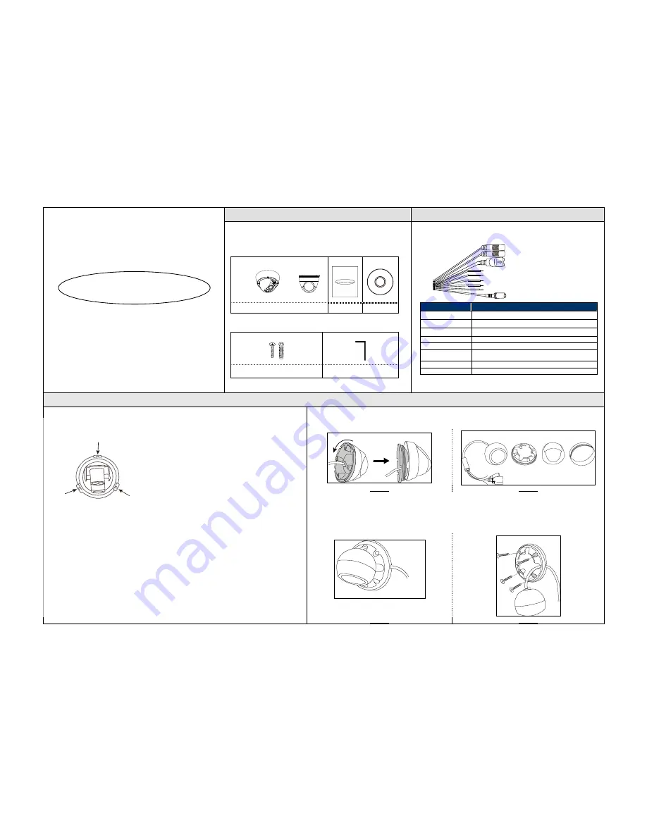
Package Content
Cable Overview
QUICK GUIDE
Please read instructions thoroughly before operation and retain it for future
reference. Online manual download:
www.surveillance-download.com/user/m521.swf
Before starting to set up your camera, please make sure items below in your box:
Standard package:
Type 1
or Type 2
Camera
Quick Guide
CD
Optional accessories
(For Type 1 only)
:
Screws & Wall Plugs x 3
Wrench
Below is an overview of various cables that can be used with the camera. Besides,
it is followed by a table, which offers simple descriptions of cable connection.
Power cable
RJ45 network cable
RESET
GND**
Alarm-out**
Alarm-in**
GND
Line-in (blue)**
Line-out (green)**
Cable
Description
Power cable
DC12V power supply.
RJ45 network cable*
Connect it to a RJ45 cable.
GND
Ground wire
Alarm-in**
Reserved for external alarm device connection
Alarm-out**
Reserved for external alarm device connection
RESET
Remove the insulating coating of wire, and twist it with a ground
wire together to reset default camera
Line-in*
Colored as blue, used to connect to a microphone for audio input.
Line-out*
Colored as green, used to connect to a speaker for audio output.
* For PoE (IEEE802.3af) installation, make sure your network cable has the maximum cable
resistance of 20
Ω
, such as CAT.5e or CAT.6 cables, to conform to the standard of IEEE802.3af.
** For Type 1 only
Installation
Type 1
Type 2
Step1: Remove the camera base as shown in
Figure 1
, and disassemble the camera to four parts as shown in
Figure 2
.
Rotate anti-clockwise
Remove
Camera lens
Part 1
Part 2
Base
Figure 1
Figure 2
Step2: Locate where you want to install this camera (wall or ceiling), and drill holes on the wall or ceiling for securing
the bracket and routing the cables (if necessary).
Step3: Attach the bracket to the wall (or ceiling), and make sure the cables are routed and arranged properly in the
bracket, as shown in
Figure 3
.
Step4: Secure the bracket to the wall (or ceiling), as shown in
Figure 4
.
Where to look
Cable routing
Attach to wall (or ceiling)
Step 1: Uncover the dome camera by loosening the screws on the housing with the supplied wrench.
Step 2: Locate the three holes as illustrated in the right picture. They are where the three supplied screws belong.
Step 3: Mark the locations of the three screw holes on the ceiling or the wall, and drill a hole for each on the
ceiling or the wall.
Step 4: Screw the camera in place.
Step 5: Power up your camera.
Step 6: Check the viewing angle on the PC.
Step 7: Adjust the position and the viewing angle of the camera, if necessary.
Step 8: Replace the dome cover and have the three screws on it tightened.
Note:
For clear images, please clear of fingerprints the inner part of the dome cover against the lens.
Figure 3
Figure 4


