background image

GENERAL INFORMATION

BASIC TEST ARRANGEMENT

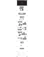
The AVB1-3 should be tested with a sampling oscilloscope with a bandwidth of at least 
2 GHz to properly observe the high-speed waveform. A typical test arrangement is 
shown below:

The AVB1-3 generates a positive pulse and a negative pulse internally. These are 
added together in the pulse combiner located on the top of the main chassis. The OUT 
P to P IN and OUT N to N IN cables shown in the diagram above are preinstalled on the 
AVB1-3 (and should never be removed).

The attenuators are required to prevent damage to the sampling oscilloscope. A 40 dB 
attenuator with sufficient voltage rating should be used on the main output.

6

AVTECH

AVB1-3

OUT N

SAMPLING

OSCILLOSCOPE

BW > 5 GHz

50 OHM INPUT

TRIG

TTL-LEVEL

LOGIC

PULSER

TRIG

MAIN OUTPUT

SYNC OUTPUT

40 dB

ATTENUATOR

ALL CABLES: 50 OHM COAXIAL

+3V to +5V (TTL)

0V

PW ≥ 50 ns 

PRF ≤ 100 kHz

+15V DC

POWER

SUPPLY

50Ω FEED-THROUGH

TERMINATOR

(OPTIONAL, BUT

RECOMMENDED)

OUT P

P IN

N IN

OUT

N/C

T

PW

50Ω TERMINATOR

(PASTERNACK PE6071

OR EQUIVALENT, INCLUDED)

Summary of Contents for AVB1-3

Page 1: ... Y S T E M S L T D N A N O S E C O N D W A V E F O R M E L E C T R O N I C S S I N C E 1 9 7 5 P O BOX 265 OGDENSBURG NY U S A 13669 0265 TEL 888 670 8729 USA Canada or 1 613 686 6675 Intl FAX 800 561 1970 USA Canada or 1 613 686 6679 Intl info avtechpulse com http www avtechpulse com X BOX 5120 LCD MERIVALE OTTAWA ONTARIO CANADA K2C 3H4 ...

Page 2: ...lace said defective item This warranty does not apply to units which have been dissembled modified or subjected to conditions exceeding the applicable specifications or ratings This warranty is the extent of the obligation assumed by Avtech with respect to this product and no other warranty or guarantee is either expressed or implied TECHNICAL SUPPORT Phone 888 670 8729 USA Canada or 1 613 686 667...

Page 3: ...TIONS 5 GENERAL INFORMATION 6 BASIC TEST ARRANGEMENT 6 CONTROLS 7 TRIMPOT ADJUSTMENTS 7 OTHER GENERAL OPERATING NOTES 7 PERFORMANCE CHECK SHEET 9 Manual Reference fileserver officefiles instructword avb AVB1 3 edition2 odt Last modified August 23 2010 Copyright 2010 Avtech Electrosystems Ltd All Rights Reserved 3 ...

Page 4: ...ut is designed to drive 50Ω loads A 50Ω load is required for proper operation The output is AC coupled This instrument is intended for use in research development test and calibration laboratories by qualified personnel AVAILABLE OPTIONS The AVB1 3 is available with these options AK1 Option an accessory kit that consists of three SMA 18 GHz 2 Watt attenuators 10 20 30 dB and two 50 Ohm 1 GHz 1 Wat...

Page 5: ...lts 50 to 500 ns TTL Connectors Out SMA In SMA Power Solder terminals Power requirements 15 Volts 400 mA Dimensions 43 x 76 x 152 mm 1 7 x 3 x 6 Chassis material cast aluminum blue enamel Temperature range 5 C to 40 C 1 May be tuned either by front panel one turn control or by applying 0 to 10 Volts DC to a solder terminal Input impedance greater than 10 kilohms 2 A 50 Ohm load is required Other l...

Page 6: ... cables shown in the diagram above are preinstalled on the AVB1 3 and should never be removed The attenuators are required to prevent damage to the sampling oscilloscope A 40 dB attenuator with sufficient voltage rating should be used on the main output 6 AVTECH AVB1 3 OUT N SAMPLING OSCILLOSCOPE BW 5 GHz 50 OHM INPUT TRIG TTL LEVEL LOGIC PULSER TRIG MAIN OUTPUT SYNC OUTPUT 40 dB ATTENUATOR ALL CA...

Page 7: ...trolled by a voltage applied to the solder terminal adjacent to the INT EXT switch This user generated voltage may be adjusted from 0 to 10V corresponding to a center frequency range of 400 to 900 MHz The 15V and GND power terminals are on the opposite face of the module TRIMPOT ADJUSTMENTS The ten turn trim pots PW and T control the pulse widths PW and pulse separation T of the positive and negat...

Page 8: ...to the sampling scope of less than one volt 3 The module shown should be bolted to a heat sink capable of dissipating at least 5 Watts 4 Various settings are sensitive to variations in the 15 VDC voltage supply and therefore a well regulated DC supply is required 8 ...

Page 9: ...PERFORMANCE CHECK SHEET 9 ...

Reviews: