


Switching Inputs
There are three ways to switch inputs on the unit: using the input selector button
on the front panel, using the remote control, and using the RS-232
communication port. An audible click will be heard whenever there is a change in
the power state of the unit.
Using the Input Selector Button
- Pressing the input selector button on the front panel will select the next
input following the active input. The green LED on the front panel will
designate the input that is presently selected.
- (NOTE: Refrain from holding the input selector button down for a
period longer than two seconds. See pages 10-12 for details.)
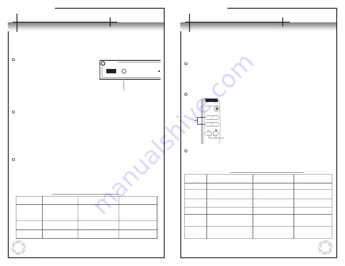
Using the Remote Control
- The direct input keys can be used to select
the corresponding input on the unit. The
green LED on the front panel will designate
the input that is actively selected.
- The + and – keys can also be used to select
inputs. By pressing the + key, the unit will
switch to the next input following the one
actively selected. By pressing the – key, the
unit will move to the input preceding the one
actively selected.
Using the RS-232 Communication Port
- Through the RS-232 communication port, the user can select a
respective input by entering one of the following codes to coordinate
with the desired task.
Changing the Unit’s Power State
Once the unit is plugged in, the power state can be changed in one of the following
three ways. An audible click will be heard whenever there is a change in the power
state of the unit.
Using the Input Selector Button
- Pressing the input selector button
on the front panel once while the
unit is turned off will power the unit
on. The last known active input will
be selected and will be indicated by
the green LED on the front panel.
- (NOTE: Do not hold the input
selector button down for a period
longer than two seconds. See
pages 10-12 for details.)
Using the Remote Control
- Pressing the power key on the remote control will cause the unit to turn
on or off depending on its current power state.
- When turning the unit on, the last known active input will be selected and
will be indicated by the green LED on the front panel.
- Pressing any of the direct input keys on the remote while the unit is off
will cause the unit to power on with that selected key’s input becoming
active immediately.
- Pressing either the + or – key on the remote while the unit is off will
cause the unit to turn on with the last known active input selected.
Using the RS-232 Communication Port
- Through the RS-232 communication port, the user can change the power
state by entering one of the following codes to coordinate with the
desired task.
AVLinx
Inputs
1
9
8
Operations
Operations
RS-232 Power State Commands
Command
Function
Response Verbose
On
Response Verbose
Off
PT<cr>
P1<cr>
P0<cr>
Toggle On/Off
Turn power on
Turn power off
AP<cr><lf>
AP<cr><lf>
AP<cr><lf>
Py<cr><lf>where y
is the new power
state
P1<cr><lf>
P0<cr><lf>
(See Appendix B on page 17-18 for more details on the
RS-232 operations.)
1
3
4
2
Direct
Input
Keys
Input
Selector
Keys
RS-232 Input Selection Commands
(See Appendix B on page 17-18 for more details on the
RS-232 operations.)
I1<cr><lf>
I2<cr><lf>
I3<cr><lf>
I4<cr><lf>
Ix<cr><lf>, where x is
the new input
Ix<cr><lf>, where x is
the new input
AI<cr><lf>
AI<cr><lf>
AI<cr><lf>
AI<cr><lf>
AI<cr><lf>
AI<cr><lf>
Function
Response Verbose
On
I1<cr>
I2<cr>
I3<cr>
I4<cr>
I+<cr>
I-<cr>
Response Verbose
Off
Command
Increment active input
by 1
Decrement active
input by 1
Switch active input to 1
Switch active input to 2
Switch active input to 3
Switch active input to 4
Input
Selector
Button


