background image


-  41  -


Single view


Drag an IPS-TX device card to background. 


Drag an IPS-RX device card to rectangle.


Multi-view


Drag an IPS-TX device card to a desired rectangle.


Drag an IPS-RX device card to background.


Wall view


Drag an IPS-TX device card to background.


Drag an IPS-RX device card to a desired rectangle.


After dragging IPS-TX and IPS-RX device cards, then select one of rectangles (click 
on it), the 

Layout


device


info 

area will show the configured information.


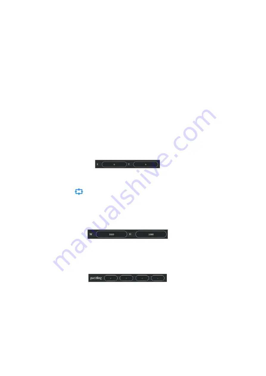
Adjust 

X

 and 

Y

 coordinates of the rectangle.


Figure 7-21 Rectangle coordination setting


Click Grid toggle 

  under Canvas Edit Area, makes it easier to align rectangles 

by giving you a visual grid line.


Edit width and height of the selected rectangle. 


Figure 7-22 Rectangle width and height setting


Adjust 

padding

 to create extra space within layout.


Figure 7-23 Layout padding setting


Summary of Contents for IPS-M

Page 1: ...1...

Page 2: ...fter a prolonged period of non use to avoid damage to the equipment Do not stand on any device while installing the device to the rack Do not attempt to maintain the device by yourself any faults plea...

Page 3: ...Connection 20 5 1 IPS TX IPS RX Connections 20 5 2 IPS TX IPS RX for KVM 21 5 3 IPS TX IPS RX for Video Wall 22 5 4 IPS TX IPS RX for Matrix Switch 23 5 5 IPS TX IPS RX for Multi view 24 5 6 Audio Rou...

Page 4: ...view 39 7 3 5 Wall 39 7 3 6 Create a New Multi view Wall view Layout 40 7 3 7 Edit Layout 40 7 3 8 Delete Layout List 44 7 4 Show 44 7 4 1 Show Component 45 7 4 2 Edit Show 49 7 5 Schedule 51 7 5 1 Sc...

Page 5: ...ion connections 23 Figure 5 5 Multi view application connections 24 Figure 5 6 IPS TX I2S audio output routing 25 Figure 5 7 IPS TX I2S audio input routing 25 Figure 7 1 IPS M information 27 Figure 7...

Page 6: ...list item 43 Figure 7 30 Popup window of delete layout 44 Figure 7 31 SHOW configuration 44 Figure 7 32 Show list 45 Figure 7 33 Create Show window 46 Figure 7 34 Layout List of show 46 Figure 7 35 L...

Page 7: ...igure 7 60 DEVICE configurations screen 58 Figure 7 61 Device basic information 58 Figure 7 62 Device network information 58 Figure 7 63 Device others information of IPS TX 59 Figure 7 64 FPS selector...

Page 8: ...creased I O flexibility and built in scalability Based on this structure AVLink controller IPS M provides an efficient way to configure the AV over IP system upon IPS TX and IPS RX This IPS M is an AP...

Page 9: ...8 1 2 IPS TX Figure 1 1 IPS TF Figure 1 2 IPS TC...

Page 10: ...9 1 3 IPS RX Figure 1 3 IPS RF Figure 1 4 IPS RC...

Page 11: ...10 1 4 IPS M Figure 1 5 IPS M...

Page 12: ...11 1 5 Packing or IPS TC IPS TF x 1 or IPS RC IPS RF x 1 IPS M x 1 Power Adapter x 2 User Manual x 1...

Page 13: ...100 milliseconds Audio Routing Lossless audio transmission HDMI downmixed stereo channel 1G Control Interface Extension of Gigabit Ethernet data network Built in Ethernet switch connects 1GbE Ethernet...

Page 14: ...HDR Connector HDMI type A EDID Read Display EDID HDCP IPS TX IPS RX HDCP HDCP 2 2 1 4 Compliant AUDIO INPUT OUTPUT IPS TX Audio Format Analog L R Connector 3 5mm Jack AUDIO OUTPUT IPS RX Audio Format...

Page 15: ...2A CASE Dimensions LxDxH 210 mm L x 114 mm W x 25mm H Construction Aluminium enclosure with black textured paint finish Weight 380g IPS TX 390g IPS RX IPS M Specifications VIDEO OUTPUT Video Formats...

Page 16: ...nal Format USB 3 1 GEN1 Connector Type A USB Signal Format USB Type C Connector Type C ETHERNET Ethernet Speed 10 100 1000 Base T Connector RJ 45 POWER CONSUMPTION Voltage 12V DC Current Max 2A CASE D...

Page 17: ...OMPONENTS 4 1 Front Panel These LEDs on the front panel specify the status of Power Video data Network packet and USB routing Figure 4 1 IPS TX front panel Figure 4 2 IPS RX front panel Figure 4 3 IPS...

Page 18: ...eo Streaming USB PAIR Yellow Bright USB chip is paired Yellow Blink USB chip is not paired Off No USB chip FW loaded USB STREAMING Yellow Blink USB data traffic present Off No USB data traffic present...

Page 19: ...DP It supports 10G network interface including either 10GBaseT or SFP Figure 4 4 IPS TC rear panel Figure 4 5 IPS TF rear panel IPS RX IPS RX only supports HDMI output on the rear panel It supports 10...

Page 20: ...itch through 10G fiber cable with SFP connector 10G RJ45 Connected to 10G Ethernet switch through copper cable CAT6a up to 100m RS 232 Connected to remote PC for controlling software Data routing betw...

Page 21: ...ith the specified display You can control the output templates and related configurations to specified displays among multiple signals In addition the IPS TX and IPS RX provide the feature each data s...

Page 22: ...TX IPS RX supports KVM Switch application Support USB 2 0 at full 480Mbps bandwidth for control command 10 Gbps for more USB applications Not only keyboard and mouse but flash web cameras and more Fi...

Page 23: ...o the HDMI interface of a single IPS TX Each display is connected to the HDMI interface of each IPS RX IPS TX transmits video signals to each IPS RX by 10G Ethernet switch IPS RX supports crops and sc...

Page 24: ...input image of each IPS TX can be freely switched to the specified IPS RX for output Through the routing configuration of IPS M the video signal is rendered seamlessly on realistic on the screen Figur...

Page 25: ...Multi view Multi view feature allows you to combine multiple video signal into a specified screen You can see multiple different video signals or PIP Picture in picture on one screen Figure 5 5 Multi...

Page 26: ...HDMI output of IPS RX I2S of IPS TX can be as an audio output to transmit the audio signal that comes from the HDMI input of IPS TX Figure 5 6 IPS TX I2S audio output routing When the I2S of IPS TX i...

Page 27: ...sary to power off or restart IPS TX IPS RX and IPS M you have to 1 Unplug the IPS TX RX M power cable 2 Wait a few seconds and plug IPS TX RX M power cable back and restart them 6 2 Hot Plugging The I...

Page 28: ...up each IPS TX and IPS RX devices for video and audio routing TV Wall building and other functions Moreover a build in website in the IPS M provides simple operations for you to quickly configure the...

Page 29: ...the build in website and start to configure the system please follows steps as below 1 Connect your PC to switch by Ethernet cable 2 Open the supported browser and enter the URL of the build in websi...

Page 30: ...ion includes ROUTING LAYOUT SHOW SCHEDULE and DEVICE configurations Routing is the main page described as below Figure 7 3 ROUTING configuration In the ROUTING configuration screen it allows you to vi...

Page 31: ...s a few seconds to switch between different IPS TX Fast switch Select this mode to configure IPS RX to quickly switch video between different IPS TX but IPS RX does not promise displayed video is sync...

Page 32: ...g output 3 Analog Analog Analog input Analog output 4 Analog HDMI Analog input HDMI output HDMI HDMI Analog HDMI can t be configured at the same time HDMI Analog Analog Analog can t be configured at t...

Page 33: ...n You can configure USB routing between IPS TX and IPS RX in this page 7 2 5 IR Figure 7 8 IR type in ROUTING configuration The IR is a bi direction interface through which signals can be transmitted...

Page 34: ...you can configure output layout upon the provided features 7 3 1 Layout component 7 3 1 1 Layout Template Click Add button on the top of Layout file list it will popup Layout Template window allowing...

Page 35: ...cludes Single view Multi view and Wall view types Click a layout to display the design of it in the Canvas Edit Area The Delete button allows you to delete the layout from system The Edit button can c...

Page 36: ...After selecting a layout you can use Canvas Edit Area to start editing content In this area you can select the General mode or the precise Grid mode by clicking the Grid toggle button as shown below...

Page 37: ...resulting in a disjointed image that is not continuous across all displays With Bezel Compensation setting it can produce a more continuous image across the displays and provides a more realistic expe...

Page 38: ...ut configuration screen shows you the IPS TX device card list and the bottom of Layout configuration screen shows the IPS RX device card list IPS TX device card Figure 7 14 IPS TX device card IPS RX d...

Page 39: ...Layout Template window Current Existing layout file you have edited 7 3 3 Create a New Single View Layout 1 Click ADD button in Layout File List 2 Select Single mode from Side bar 3 Enter layout name...

Page 40: ...ew Layout Template window Template Most common Multi view layout templates Customize Using drag features to create your own layout 7 3 5 Wall Figure 7 18 Wall view Layout Template window Template Most...

Page 41: ...field 4 Select a Template or Customize 5 Click Confirm button 7 3 7 Edit Layout Set IPS TX and IPS RX devices in the layout by dragging device card into rectangle in Canvas Edit Area Below figures sho...

Page 42: ...IPS TX and IPS RX device cards then select one of rectangles click on it the Layout device info area will show the configured information Adjust X and Y coordinates of the rectangle Figure 7 21 Rectan...

Page 43: ...view layout Figure 7 25 Routing mode selection of rectangle in Single view layout Adjust Bezel to create space around the rectangle in Wall view layout Figure 7 26 Bezel setting of rectangle in Wall v...

Page 44: ...43 Zoom out Zoom in Figure 7 28 Effect of zoom out and zoom in Click the file list Edit button you can re select layout template Figure 7 29 Layout File list item Click Confirm button to save and send...

Page 45: ...popup Delete layout message Click Delete button to cancel layout Figure 7 30 Popup window of delete layout 7 4 Show In the SHOW configuration screen you can set the layout playback time and add effect...

Page 46: ...45 7 4 1 Show Component 7 4 1 1 Show List Show List lists the shows that have been set Figure 7 32 Show list...

Page 47: ...will popup Create Show window Enter the show name and configure the duration to play Then click confirm button to create a show Figure 7 33 Create Show window 7 4 1 3 Layout List Layout List lists lay...

Page 48: ...ow Select one of saved layouts to play from the library then click Confirm button Figure 7 35 Layout Library window 7 4 1 5 Layout Detail The Layout Detail shows the thumbnail of selected layout in La...

Page 49: ...wap Effect View Swap Effect is used to switch displayed video between two IPS RX devices at specific moment Click to add a View Swap Effect or delete to clear settings Figure 7 38 View Swap Effect lis...

Page 50: ...how list you can rename and reset duration Figure 7 41 Show edit window Select timeline item click on it then you can move or delete it Timeline item Layout is resizable you can increase or decrease t...

Page 51: ...43 Timeline item dragging You can change the way of timeline axis display by scrolling the mouse wheel over the timeline Figure 7 44 Timeline axis display adjustment Drag timeline to the left or right...

Page 52: ...Schedule In the SCHEDULE configuration screen the calendar shows you the show playback schedule Click on Today on the upper left corner to quickly switch to today s schedule Figure 7 46 SCHEDULE confi...

Page 53: ...Month and Agenda View 7 5 1 1 Day View Switch View tab to Day item it will navigate to Day View Figure 7 47 Day View in SCHEDULE configuration 7 5 1 2 Week View Switch View tab to Week item it will n...

Page 54: ...w tab to Month item it will navigate to Month View Figure 7 49 Month View in SCHEDULE configuration 7 5 1 4 Agenda View Switch View tab to Agenda item it will navigate to Agenda View Figure 7 50 Agend...

Page 55: ...Week View Double click at a time or in the All Day section at the top then fill in the popup New Event window Figure 7 51 New Event window Start End Time Field If the All day event is selected the St...

Page 56: ...day event is unselected the Start and End time field will display both Date and Time picker icons Figure 7 53 Time picker in New Event window Daily Repeat Option Figure 7 54 Daily repeat option in Ne...

Page 57: ...igure 7 55 Weekly repeat option in New Event window Monthly Repeat Option Figure 7 56 Monthly repeat option in New Event window Yearly Repeat Option Figure 7 57 Yearly repeat option in New Event windo...

Page 58: ...day event selection and description about the show Figure 7 58 Edit Event window 7 5 1 7 Delete Event Click Delete button of an event it will popup Delete event message to confirm Figure 7 59 Delete e...

Page 59: ...onfigured devices Figure 7 60 DEVICE configuration 7 6 1 Device Component 7 6 1 1 Device Edit device name here Figure 7 61 Device basic information 7 6 1 2 IP Select DHCP to configure IP Gateway and M...

Page 60: ...ion of IPS TX FPS Frames per second selector Select the number of times that the image on the screen is refreshed each second Figure 7 64 FPS selector of IPS TX HDCP selector HDCP is designed to preve...

Page 61: ...original or scaled video source resolution when routing video in Genlock mode and ratio adjust method in Fast Switch mode Figure 7 66 Device others information of IPS RX Resolution selector Figure 7...

Page 62: ...g Info Click the top tabs to get the information of each interface including Video Audio RS 232 USB and IR Figure 7 71 Device Streaming info 7 6 1 5 Delete Erase Device Online IPS TX IPS RX device car...

Page 63: ...ne IPS TX IPS RX device card The indicator on the upper left corner is off Right click to Delete device from your configuration The device is still connected not configured Figure 7 73 Offline device...

Page 64: ...63 CHAPTER 8 TROUBLESHOOTING Make sure that all cables are securely attached and seated completely in their socket before solving the problems...

Reviews: