


Industrial Dobby Loom User's Manual
Shuttle Box System
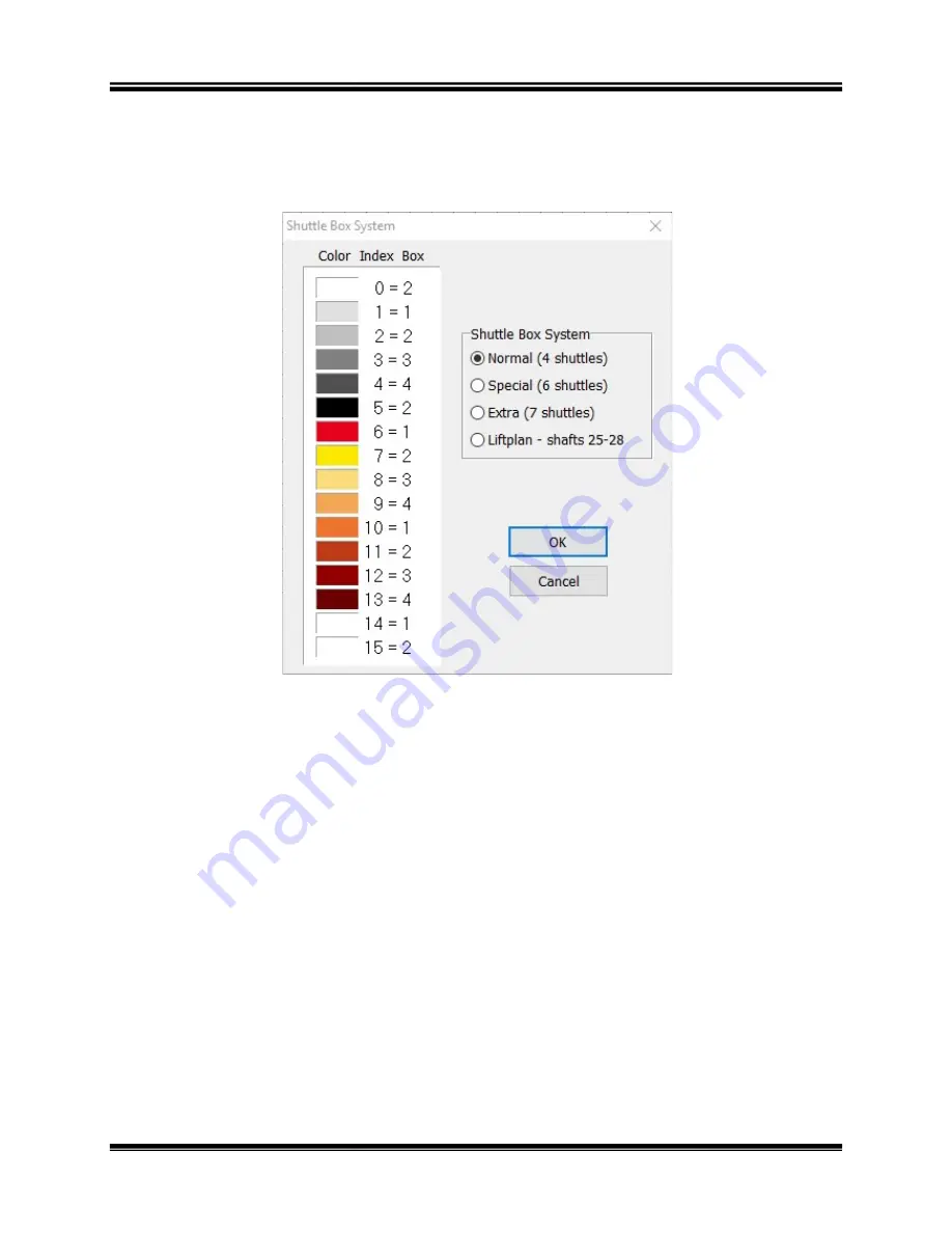
Normal Mode
NORMAL
is the mode used for most weaving and is the simplest
understand.
Shuttles move from box 1 on one side to box 1 on the other side;
to box 2; from box 3 to box 3; and from box 4 to box
on both sides move up and down
While any of the indexed colors can be used, it is usually s
first five indexed colors (0
If desired, you can change the color associated with any index Number to
the color you
will actually be using by employing the Color
If you are using one color and one shuttle, use the color with
0 and place the shuttle in box 2
Industrial Dobby Loom User's Manual
is the mode used for most weaving and is the simplest
Shuttles move from box 1 on one side to box 1 on the other side;
to box 2; from box 3 to box 3; and from box 4 to box 4.
The Shuttle boxes
on both sides move up and down together.
While any of the indexed colors can be used, it is usually simplest to
first five indexed colors (0-4) to indicate the color usage in the pattern draft.
change the color associated with any index Number to
will actually be using by employing the Color Dialog.
ng one color and one shuttle, use the color with index
0 and place the shuttle in box 2 -- either right or left.
Using the IDL
Page | 41
is the mode used for most weaving and is the simplest to
Shuttles move from box 1 on one side to box 1 on the other side; from box 2
The Shuttle boxes
implest to use the
indicate the color usage in the pattern draft.
change the color associated with any index Number to
Dialog.
index Number
Summary of Contents for Industrial Dobby Loom
Page 2: ......
Page 6: ......
Page 10: ......
Page 11: ...Industrial Dobby Loom User s Manual IDL Setup IDL Setup Page 5 IDL SETUP IDL SETUP ...
Page 22: ......
Page 53: ...Industrial Dobby Loom User s Manual Maintenance Maintenance Page 47 MAINTENANCE MAINTENANCE ...
Page 56: ......
Page 64: ......


