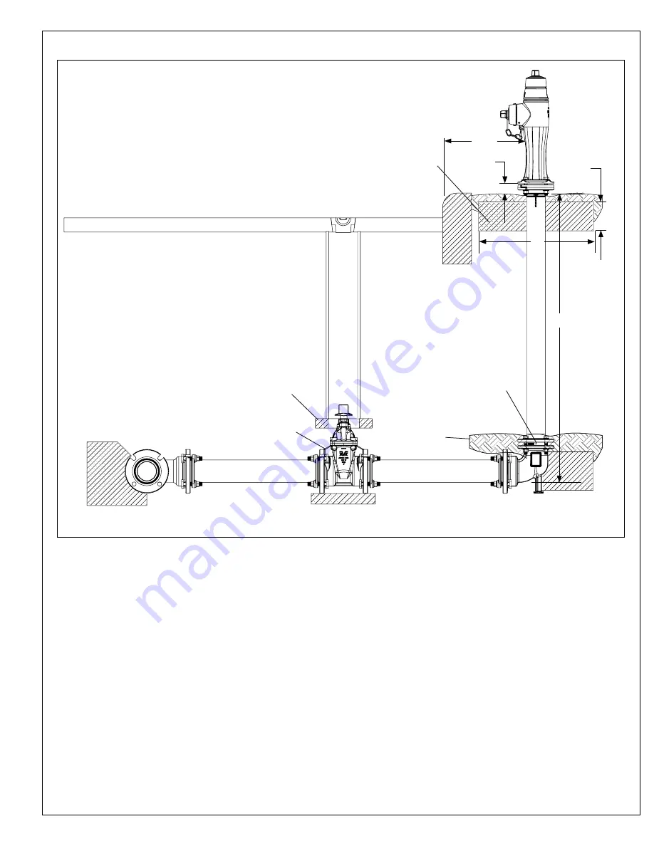
background image

page 4

Fig. 1 

Hydrant Installation

C o n c r e t e 

thrust block

Concrete

Curb

Concrete  collar  for  protection  on  all 

hydrant installations.

Drain Detail:

Caution:  When  pouring 

thrust block, do not cover 

drain holes. 

1/3 cubic yard drain field 

rock.

C o n c r e t e 

thrust block

Supply Valve

6"

2' min.

2" min.

2'

Bury

Concrete

Summary of Contents for 67 Series

Page 1: ...ASSEMBLY PARTS LIST INTRODUCTION DESCRIPTION RECEIVING AND STORAGE INSTALLATION AND TESTING INSTALLATION TESTING OPERATION AND MAINTENANCE HYDRANT TOOLS OPERATION MAINTENANCE PROCEDURES LUBRICATION INSPECTION DISASSEMBLY FOR INSPECTION REASSEMBLY AFTER INSPECTION REPAIR PROCEDURES NOZZLE REPLACEMENT TRAFFIC REPAIR KIT MAIN VALVE REPLACEMENT OPTIONAL EQUIPMENT EXTENSION KITS TROUBLESHOOTING GUIDE P...

Page 2: ...7 Post Flushing Hydrant Exploded Parts Breakdown F1 F2 F59 F52 F76 F500 F75 F501 F504 F506 F31 F505 F31 F34 F503 F73 F509 F506 F31 F73 F7 F515 F7 F514 F507 F38 F508 F516 F519 F21 F19 F24 F510 F518 F23 F502 F517 F31 F34 F73 F20 F22 ...

Page 3: ...y F500 Operating Nut Copper Alloy F501 Anti Friction Washer Copper Alloy F502 Stem Seal O ring NBR F503 Upper Stem Rod 304 Stainless steel F504 Nozzle Section Ductile iron ASTM A536 F505 Two Piece Breakable Flange Ductile iron ASTM A536 F506 Nozzle Section Bolt Zinc Plated Steel F507 Coupler Pin 304 Stainless steel F508 Breakable Coupling 304 Stainless steel F509 Lower Barrel Ductile iron ASTM A53...

Page 4: ...and dry and the main valve should be closed until installed to prevent weather related damage For long term storage the hydrants should be stored indoors INSTALLATION AND TESTING NOTE American AVK recommends AWWA Standard C600 and AWWA Manual M17 for further information regarding hydrant installation and testing NOTE Consult local codes and standards for proper fire hydrant placement and spacing W...

Page 5: ...t block Concrete Curb Concrete collar for protection on all hydrant installations Drain Detail Caution When pouring thrust block do not cover drain holes 1 3 cubic yard drain field rock C o n c r e t e thrust block Supply Valve 6 2 min 2 min 2 Bury Concrete ...

Page 6: ...mpress the air and cause a safety hazard AAVK comment underlined as very important 6 Check for leakage at flanges outlet nozzles and the packing or O rings around the stem 7 If leakage is noted repair or replace the faulty components or the entire hydrant AAVK comment only after hydrant is closed and all pressure is bled off 8 Repeat the test until results are satisfactory PRESSURE TEST AT PRESSUR...

Page 7: ...eplacement 67 065 59 Series 67 Hydrant Wrench for Thrust Nut removal replacement 67 080 59 hydrant operation and Cap removal replacement METRIC AND INCH WRENCH REQUIREMENTS FOR AMERICAN AVK HYDRANTS PART INCH SIZE METRIC SIZE Weathershield Retaining Bolt Allen 5 16 8mm Thrust Nut Retaining Screw Allen 5 32 4mm Nozzle Retaining Screw 3 16 5mm All other Bolts and Nuts 15 16 24mm ...

Page 8: ...ld F2 until the Main Valve F518 hits the stop in the hydrant Base F519 Do not force the hydrant in the opening direction beyond full open as indicated by sudden resistance to turning If water does not flow when the hydrant is open it is probably due to a closed valve upstream from the hydrant 3 To close turn the operating nut until the Main Valve stops the flow It is not necessary to close this st...

Page 9: ...athershield bolt has been loosened to prevent damage to the internal O rings Refilling is performed by loosening the Weathershield bolt F1 with a 5 16 or 8mm hexagon key Refill lubricant reservoir with a food grade grease using a grease gun on the Zerk Fitting F75 Tighten the Weathershield Bolt F1 Servicing should be checked and performed at least once per year if required or per local municipal r...

Page 10: ...le It is located approximately in from the edge of the nozzle section and at about the 4 30 to 5 00 o clock position If this retaining screw is missing ensure that the nozzle is correctly installed as shown in Fig 4 then immediately replace it F23 Setscrew M10 x 16 304 stainless steel with a 5mm or 3 16 hexagon key 3 There should be a small dimple or punch mark on the hose nozzle F20 this mark sho...

Page 11: ...AVK Series 67 hydrant wrench remove the Operating Nut F500 and Anti Friction Washer F501 See Fig 7 6 Using 15 16 or 24mm wrenches remove the Nozzle Section Bolts F506 Washers F31 and Nuts F34 Set the Two Piece Breakable Flange F505 aside with the hardware Lift the Nozzle Section F504 assembly up over the Upper Stem Rod F503 Also remove the Flange O ring F73 See Fig 8 7 Remove the lower Springpin F...

Page 12: ...F500 F501 F505 F31 F34 F31 F506 F504 F38 F507 F508 Series 67 T Wrench F517 F516 F518 F515 F7 F510 page 11 DISASSEMBLY FOR INSPECTION continued MAIN VALVE INSPECTION Fig 5 Fig 6 Fig 7 Fig 8 Fig 9 Fig 10 Fig 11 Fig 12 ...

Page 13: ...n 5 The Cap Nozzle assembly can now be removed for inspection from the Nozzle Section Check the Hose Nozzle Gasket F21 and the Hose Nozzle O ring F22 for damage and replace if necessary 6 To replace screw the Hose Nozzle Cap with the Hose Nozzle Cap Gasket installed on to the nozzle Lightly grease the Hose Nozzle O ring and insert the Cap Nozzle assembly into the Nozzle Section making sure that th...

Page 14: ... 2 Using the AVK Series 67 Hydrant Wrench fully open the hydrant to allow better access to the lower end of the Upper Stem Rod F503 Visually inspect the Upper Stem Rod for damage Remove the Breakable Coupling F508 Coupling Pins F507 Springpins F38 from the Upper Stem Rod 3 Refer to the MAIN VALVE INSPECTION procedures on page 10 to remove the Nozzle Section from the Upper Stem Rod 4 If still prese...

Page 15: ...l 10 Secure the Two Piece Breakable Flange as shown in Fig 15 with the text This Side Up with the lip of the Breakable Flange below the shoulder of the Lower Barrel 11 Follow the disassembly steps in DISASSEMBLY FOR INSPECTION MAIN VALVE INSPECTION in reverse order for reassembly pages 10 11 Note Torque the nozzle section hardware to 60 Ft Lbs Two Piece Breakable Flange mounted below the shoulder ...

Page 16: ...ads Then unscrew the lower stem rod F510 just enough until the holes line up you should not unscrew the lower stem rod more than of a turn Insert the Main Valve Retainer Pin F516 into the hole Insert a Cotter Pin F517 into the retainer pin hole and bend cotter pin with pliers so that it won t come apart Grease the ears of the main valve disc with a food grade grease Note Make sure cotter pin is be...

Page 17: ...per Stem Rod assembly to the Extension Stem Rod with a Coupling Pin and Springpin NOTE Ensure that the Springpins are fully engaged on the Coupling Pins 6 Verify placement of the Flange O ring F73 on the Lower Barrel and place the Extension Barrel over the Upper Stem Rod assembly and align with the bolt holes on the Lower Barrel 7 Attach the Extension Barrel with a Standpipe Flange F511 and mounti...

Page 18: ...e Section to the desired position Tighten the mounting hardware to 60 Ft Lbs PROBLEM Hydrant opens but will not close Probable Cause The Breakable Coupling or Extension Coupling has broken or become disconnected Corrective action Remove the Nozzle Section and replace the affected Coupling PROBLEM Hydrant will not drain Probable Cause Drain holes may be plugged or blocked Corrective action Loosen t...

Page 19: ...oved from installation prior to approval from American AVK this warranty shall be void As to motors gearing or accessory equipment purchased by American AVK Company from other manufacturers and used or incorporated into American AVK Company s products those manufacturers warranties shall apply American AVK Company s sole responsibility shall be in its sole discretion to replace the product with th...

Reviews: