


INSTALLATION, OPERATION AND MAINTENANCE MANUAL – ORIGINAL VERSION
AVK GATE VALVES FOR WATER AND FIRE PROTECTION
SERIES 145
Page 7/12
MI GateValve 145 rev. AC 2020 GB
7. REPAIR PROCEDURES
In most cases, in order to keep system downtime to a minimum, complete valve assembly replacement is implemented. This
may also be preferable due to physical access restrictions in the area of the valve. If this is the case, as in all installation/
maintenance and inspection procedures, follow all local installation and safety practices as directed by the authorities having
jurisdiction.
If system downtime is not an issue, the following procedures provide repair instructions for minor issues. Leakage, broken
parts, hard operation and other major defects should be corrected by a repair crew as soon as possible after the defect has
been reported. If repairs are to be performed in the field, the repair crew should take a full complement of spare parts to the job
site. Provisions should be made to isolate the defective valve from water pressure and relieve internal trapped pressure prior to
performing any corrective maintenance. Disassembly of the valve should be accomplished in accordance with the procedure
supplied in the following sections. After repairing the valve, the operating mechanism should be cycled through one complete
operating cycle. An inspection should be made with full line pressure applied to the valve in open position to detect leakage
in the areas around the seal plate, bonnet, packing gland and body-end connections. A record should be made to indicate
that the valve has been repaired and is in working condition. Any marking that the valve is inoperable should be removed. In
addition, fire department and other appropriate municipal departments should be informed of satisfactory repair of the valve.
7.1 NRS VALVE REPAIRS
7.1.1 WRENCH NUT REPAIR
WARNING
Although some of the following procedures can be performed
under full working line pressure, it is recommended that any
partial disassembly or maintenance will be performed with
the water main supply line shut off and after bleeding off the
pressure!
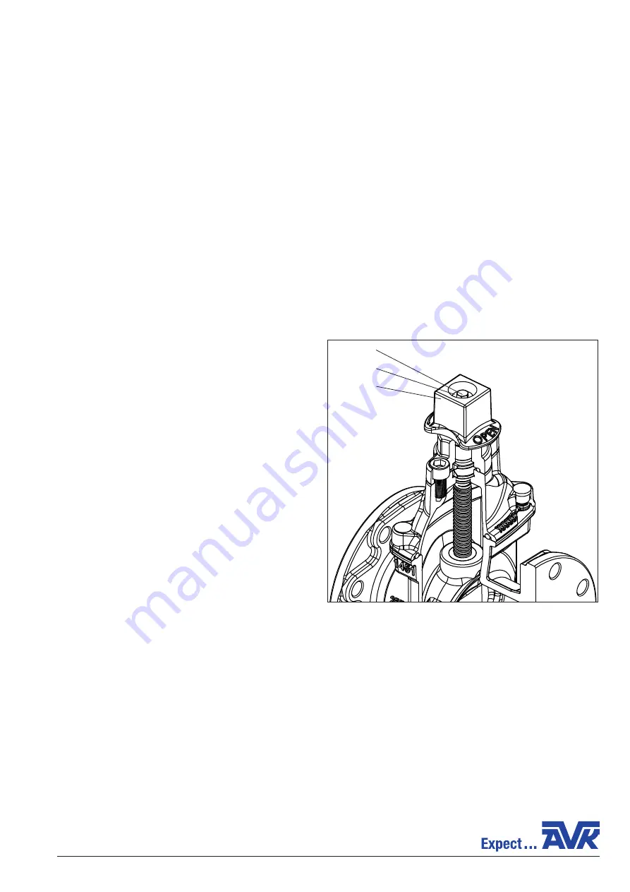
1. Remove the wrench nut bolt (F220) and wrench nut
washer (F221) using a 1/2” (13mm) wrench for DN65-100
valve sizes, and an 11/16” (17mm) wrench for DN150-200
valve sizes. Remove the wrench nut (F225) and replace
with a new one (Fig. 2A).
2. Replace the wrench nut bolt (F220) and wrench nut
washer (F221) using a 1/2” (13mm) wrench for DN65-100
valve sizes, and an 11/16” (17mm) wrench for DN150-200
valve sizes.
page 7
REPAIR PROCEDURES
In most instances, in order to keep system down time to a minimum, complete valve assembly replacement is
implemented. This also may be preferable due to physical access restrictions in the area of the valve in question. If this is the
case, as in all installation/maintenance and inspection procedures, follow all local installation and safety practices as directed
by the National Fire Protection Association, (NFPA #25 latest) and any other authorities having jurisdiction.
If system down time is not an issue, the following procedures provide repair instructions for minor issues. Leakage,
broken parts, hard operation, and other major defects should be corrected by a repair crew as soon as possible after the defect
has been reported. If repairs are to be performed in the field, the repair crews should take a full complement of spare parts to
the job site. Provisions should be made to isolate the defective valve from water pressure and relieve internal trapped pressure
prior to performing any corrective maintenance. Disassembly of the valve should be accomplished in accordance with the
procedure supplied in the following sections. After repairing the valve, the operating mechanism should be cycled through one
complete operating cycle. With full line pressure applied to the valve in the open position, an inspection should be made to
detect leakage in the areas around the seal plate, bonnet, packing gland, and body-end connections. A record should be made
to indicate that the valve has been repaired and is in working condition. Any marking that the valve is inoperable should be
removed. In addition, fire department and other appropriate municipal departments should be informed of satisfactory repair
of the valve.
NRS VALVE REPAIRS:
WRENCH NUT REPAIR:
WARNING:
Although some of the following procedures can be
performed under full working line pressure, it is recommended
that any partial disassembly or maintenance be perform with the
Water Main Supply Line shut off and pressure bled!
1. Remove the Wrench Nut Bolt (F220) and Wrench Nut Washer
(F221) using a 1/2”, (13mm) wrench, for 2 1/2” to 4” valve
sizes, and 11/16”, (17mm) wrench for 6” to 8” valve sizes.
Remove the Wrench Nut (F225), and replace with a new one.
(See Fig.3A)
2. Replace the Wrench Nut Bolt (F220) and Wrench Nut Washer
(F221) using a 1/2”, (13mm) wrench, for 2 1/2” to 4” valve
sizes, and 11/16”, (17mm) wrench for 6” to 8” valve sizes.
Fig. 3A
F220
F221
F225
Fig. 2