AviPro Aicraft, Ltd. Bearhawk N33RB Builder'S Assistance Manual Download Page 8

8

flap push rod between them to hold them in align-
ment.  Then  clamp  the  top  end  of  the  push  rod
where it bolts to the arms down to the crossmember
tube to keep it from moving while drilling it. 

The root actuating arms have to be mount-

ed at a specific angle on the torque tube to give the
flap cables the most efficient angle for pulling.

With  the  outboard  actuating  arms  still

clamped against the fore and aft tubing crossmem-
ber, position the inboard arm as per Drawing No.
14. 

Because there is limited room between the

fuselage and the wing root, it is essential that the
flap actuating arm be centered in that gap. For that
reason, it’s advisable to drill the hole through the
actuating  arm  and  torque  tube AFTER  the  wings
are on the airplane to ensure no interference occurs.
IT S RECOMMENDED THAT THE OUTBOARD
ACTUATING ARMS  BE DRILLED WITH THE
WINGS ON  THE AIRPLANE.  

Come in from the bottom (or turn the wing

over) and center punch where you’ll drill the hole
in the arms. Then drill one arm with a fresh 1/8” bit
(make it fresh, so it cuts cleanly and easily). Using
that as a guide, drill with the 11/64” and ream. Then
put a bolt in place to keep it lined up. 

Do 1/2 of the outboard arms at a time, so

one of them is finished and bolted in place, which
will  hold  the  other  one  in  position  and  eliminate
minor  mis-alignments  and  wallowed-out  holes.
These will be bolted with Nyloc nuts. 

If you want, you can install the flap springs

now, which will help hold everything under tension
and keep everything from moving. 

A Note About Drilling

The  back  side  of  every  hole  you  drill  is

bound  to  have  at  least  a  certain  amount  of  burr
standing up. The burr will be less if you use a sharp
bit and don’t  push  too  hard,  but  you’ll  still  get  a
burr. Your life will be much easier later on, if you
file off every burr you can reach, including those
inside the actuating arms. Not only does this pro-
duce a nicer looking unit with fewer stress risers
but  it  makes  putting  the  torque  tube  in  and  out
much easier. This is where a Dremel tool with a lit-
tle  sanding  drum  on  it  would  come  in  handy  for
those inside burrs.

The Flap Actuating Cable

Later, after you put the wings back on the

airplane semi-permanently and position the actuat-
ing arms and drill the mount bolt, you’re ready to
attach the actuating cable. The flap arm was deliv-
ered with a 3/16” hole (AN3) hole, however you
use  a  1/4”  shackle  rather  than  a  3/16”  shackle  to
give a longer distance at the arm, which increases
cable clearance from some structure. 

A 3/16”  (AN3)  bolt  will  be  sloppy  in  the

shackle so bush it down with short pieces of 1/4 x
.028” tubing. If you can’t find that size tubing, con-
tact AviPro. The only charge is for shipping. Later
kits have six inches of the tubing supplied.   

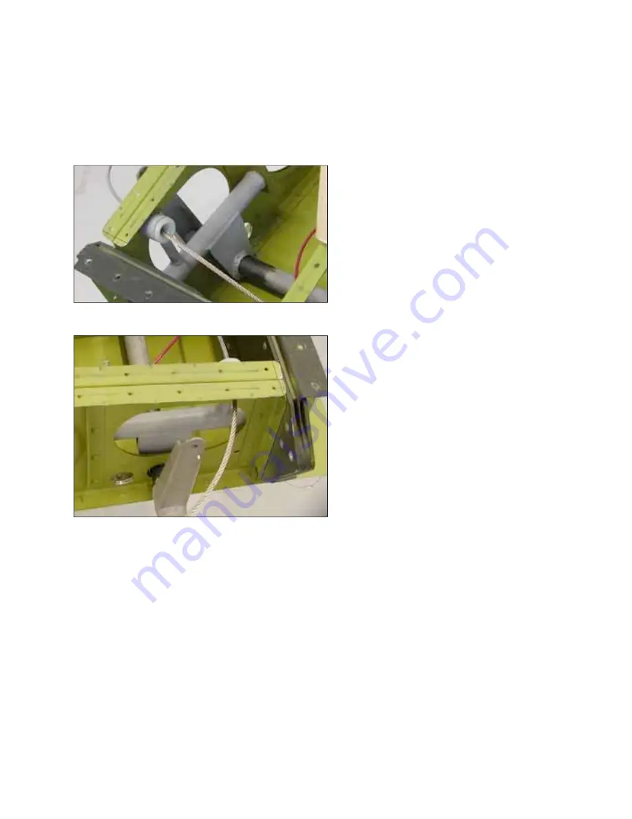
The actuating arm at the inside end of the torque tube uses a
1/4” shackle for connecting with the flap cable and it is bushed
down to 3/16” with 1/4” x .028 tubing. 

Sand the paint off the inside of the pivot bushing and the tube
and it

ll be easier to insert it and it will work much easier.

Summary of Contents for Bearhawk N33RB

Page 1: ......

Page 2: ...Cut hole in bottom skins for aux tanks if applicable 20 Install aux tank straps pump and plumbing 21 Fabricate aux tank cover install nut plates 22 Run conduit for aux tank pump and nav light wiring...

Page 3: ...m is so light don t attempt to unpack the wings in a wind because it ll pick up the big pieces of foam even as you try to get them out of the crate From this point on remember that every thing in the...

Page 4: ...70 100 30 40 80 5 16 24 100 140 225 60 85 140 3 8 24 160 190 390 95 110 240 7 16 20 450 500 840 270 300 500 The wings don t weigh very much 150 pounds but they are not only awkward but very easily da...

Page 5: ...to be made between the spar flange and the edge of the skin Use the front row of holes as guides to drill the stiffener and hold it in place while drilling the rear holes To visualize what you re tryi...

Page 6: ...heavy extruded aluminum angle 1 4 thick 2 or so wide and squeeze the rivets using the angle as both a straight edge and as an interface between the squeezer the heads of the riv ets The procedure is a...

Page 7: ...e outboard arms has to be slid in place first see photo Because both the torque tube and the bearings have been painted it s a good idea to remove the paint from both the inside of the bearings and th...

Page 8: ...l the flap springs now which will help hold everything under tension and keep everything from moving A Note About Drilling The back side of every hole you drill is bound to have at least a certain amo...

Page 9: ...able First get a cable cutter Aircraft cable is extremely hard and difficult to cut It can be cut with a cold chisel on an anvil but a dedicated cable cutter does a much better job and you re going to...

Page 10: ...trol system including the pivot bolts for the bellcrank and those attaching the cables to it are drilled bolts using castellated nuts and cotter pins Routing the Cables When routing the aileron cables...

Page 11: ...older kits if the supplied metal is flushed to the fuselage side of the root ribs it hangs into the flap bay by about 1 4 and partially covers one of the holes in the lower rear wing skin If this happ...

Page 12: ...ht Fore and aft leveling can be accomplished by measuring the angle of the top of the front door frame Because of the hinge bushing being in the way you may have to space the level out Leveling right...

Page 13: ...he same Summarized they are 1 Measure fuselage fittings to determine any difference left to right 2 Correct the angles to match by ovaling out the wing fittings in the right direction prior to drillin...

Page 14: ...hole in the rear fitting Using a round file file away just enough of the offending metal to let the rod pass though To correct the actual mounting angle of the wings we re going to correct the angle...

Page 15: ...d marking the dimension on that then measuring the marks Do the same thing for the rear spar BUT MEASURE THE HOLE ON THE FRONT FACE OF THE SPAR Now repeat exactly the same process on the other wing an...

Page 16: ...all them lifts and use that to get the exact height needed Don t forget to pad the scaffolding to prevent scratching This is a good application for the foam that the wings were packed with Or use chea...

Page 17: ...rd against the rear fitting and put a washer or washers in the gap Ideally the spacer will fill the gap com pletely so when the fitting is squeezed by a big pair of Vice Grips it won t be bent There s...

Page 18: ...t Briefly what the jig does is index one piece of tubing in the front hole of the rear fitting while you are drilling in from the rear hole and through the spar It is available from AviPro at no charg...

Page 19: ...e leveled it in last section but level it again The accuracy of your dihedral which also determines your rig ging will depend on having the fuselage level We re going to recheck it several more times...

Page 20: ...e about 79 1 4 To make your life easier it helps if the cut you make is square so your subsequent measure ments are accurate So whatever method you use chop saw horizontal hacksaw hand hacksaw make su...

Page 21: ...the strut but the top one has a slight angle We ll first determine the position of the bottom fitting drill and bolt it in place on the outside of the strut and then finalize the position of the top...

Page 22: ...s and we can do the top fitting Drill Top Fitting Holes As a last minute check to make sure nothing moved put the strut back up on the airplane with the bottom fitting bolted to the outside of the str...

Page 23: ...termine which fitting goes with which strut and what direction they were facing when they were drilled That s just good insurance Drill the Rest of the Holes Reach inside the struts with 320 grit pape...

Page 24: ...u ll have to remove the gussets that have been temporarily pop riveted over the hing ing areas both top and bottom Don t forget to number the gussets before drilling them loose and have a corre spondi...

Page 25: ...here s the possibility you may find a hinge mount the wing part that is angled slightly wrong and may need spacers under its feet but that s not likely If you do use wide area AN 970 washers as a shim...

Page 26: ...at have yet to be completed but will be in due time They are Pouring lead in the aileron balance tubes Final riveting the trailing edges Balancing the Ailerons This can be done at any time after the a...

Page 27: ...here will be less air space in it If you can find number 12 shot great MAKE SURE IT IS LEAD BECAUSE SOME PLACES SELL STEEL SHOT WHICH ISN T HEAVY ENOUGH Although some builders have made up a paste of...

Page 28: ...of getting weight in there is stuffing the tube full of lead wool This looks like steel wool but it is lead and is available from McMaster Carr The method of installation involves nothing more than f...

Reviews: