background image

 S6L-24C and S6L-16C

17

S6L-24C/16C Only

2

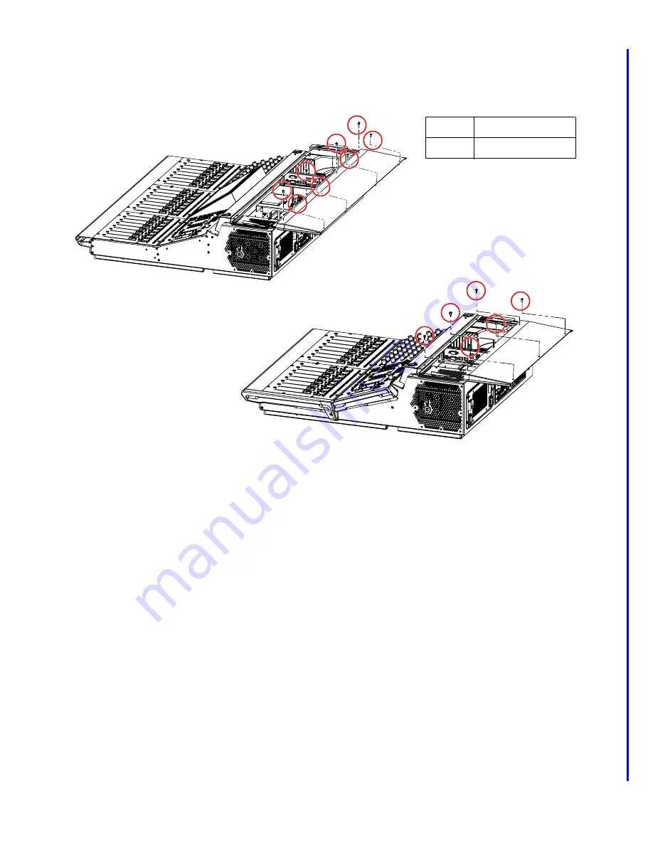
Using a 2.5mm Hex driver, remove the fasteners that secure the back edge of the back cover to the S6L chassis and set the screws 
aside. 

• S6L-24C uses 8 fasteners
• S6L-16C uses 6 fasteners

3

After removing the fasteners try sliding the back cover off the chassis by pushing it down with your hands and simultaneously 
pulling the cover away from the chassis. 

4

Slide the panel away from the control surface, and set the panel aside. 

Figure 23. Back Cover fasteners on S6L-24C (above) and S6L-16C (below)

Fasteners: 

Tool: 

M4x8mm BHCS

2.5mm Hex driver

Summary of Contents for S6L Control Surface

Page 1: ...1x 2 Phillips screwdriver for S6L 16C only 12 inch magnetic tip 2 Phillips recommended 1x 9 32 nut driver or small open end wrench S6L 24C and 16C Only Large towel or similar on which to set the MTS S6L 24C only or Top Cover S6L 16C only System Restore USB drive created to install VENUE software v6 2 or later after replacing the SBC see the VENUE S6L In stallation Guide for instructions on how to ...

Page 2: ...y 4 Install the New SBC Secure the new SBC to the Tray Reconnect all cables Re install the Tray into the chassis 5 Complete the Installation Perform a System Restore on the control surface Pair the new SBC to the engine and re establish the control surface configuration Confirm successful installation Reassemble the control surface back cover and other components Identifying Procedures for Your Co...

Page 3: ... work area is clear of any debris 1 Prepare the S6L Control Surface Prepare the S6L control surface by removing the lower and upper back covers The steps required to remove the back cover vary depending on the model of S6L control surface To remove the lower back cover from S6L 24D 32D or 48D 1 Using a 2 5mm Hex driver remove the fasteners that secure the back cover to the S6L chassis and set the ...

Page 4: ...ratching the chassis first remove both end caps At minimum one End Cap needs to be loosened enough to let you remove the top cover later in these instructions If you remove either or both of the End Caps completely carefully disconnect the LED power cable before moving the cap s away from the chassis Next use a 2 Phillips screwdriver and remove one of the small retaining brackets 3 Slide the panel...

Page 5: ...ve the upper back cover by removing its fasteners and then lifting the cover away S6L 24D uses 13 fasteners S6L 32D uses 16 fasteners S6L 48D uses 22 fasteners 5 Proceed to 2 Remove the SBC Tray Figure 4 Removing the upper back cover S6L 32D shown S6L 24D 32D 48D ...

Page 6: ... Set the fasteners aside to use later when you reinstall the shroud 3 Locate the captive screws securing the SBC Tray to the chassis these are in addition to the captive screw under the shroud that you loosened earlier S6L 24D 32D and 48D have four captive screws to loosen shown below Figure 5 Shroud access hole for captive screw below Figure 6 Fasteners to remove from the top of the shroud Though...

Page 7: ...Tray out but you may need to guide one or more of them away to allow the Tray to be lifted out of the chassis If you find you do need more slack note and or label and then disconnect any cable that is not long enough to allow the Tray to be lifted out of the chassis 6 Being very careful to not stretch any cables use two hands to lift the tray out of the chassis Tilt the Tray as needed to clear the...

Page 8: ...cle the shroud you do not need to re install it To remove the old shroud Using a 2 Phillips screwdriver remove the purple shroud by doing the following keep all fasteners organized to reuse later Remove the screw that secures the front edge of the shroud to the Tray Remove the two screws that secure the back edge of the shroud to the Tray Remove and recycle the shroud and its fasteners The image s...

Page 9: ... fasteners aside to use later when you install the new SBC 2 Carefully pull the SBC away from its faceplate until all ports clear their openings and tabs on the faceplate then lift the old SBC out and set it aside ift the old SBC out and set it aside 3 Return reuse or recycle the old SBC cables and faceplate if present 4 Proceed to 4 Install the New SBC Figure 13 Fasteners that secure the SBC to t...

Page 10: ... or mounting bracket If your control surface does not have this bracket and faceplate it is not required to install a faceplate Installing the New SBC Onto the Tray To install the new SBC onto the Tray 1 Remove the new SBC from its packaging 2 Place new SBC in position on the Tray Be sure to orient the new SBC correctly and align it with the threaded receivers on the Tray Be sure to guide the port...

Page 11: ...ing at the back of the control surface Be sure to connect each cable to its correct port and to orient the cable as described in the table above S6L Control Surface SBC Cable Labels Congatec SBC Port IDs Cable PN newer units Source Notes X19J2 7070 30554 00 Back panel DVI X49 7070 30597 00 PDB J2 X5 J2 7070 35031 00 Switch X6 J2 7070 35029 00 Back panel ECx RJ45 X39J2X 7070 30621 00 Carbon 2 J32 X...

Page 12: ...u closest to the back of the control surface Also be sure to secure the LVDS cable using the cable clamp you removed earlier Cables for Port X16 Two cables connect to the two separate connectors on port X16 one to the upper half of the port and one to the lower Be sure to connect each cable to the correct port and to orient each cable as shown below with the black wires to the right Figure 16 S6L ...

Page 13: ... complete instructions refer to the VENUE S6L Installation Guide pdf available for download from your Avid account or from the S6L Documentation article on our Knowledge Base The System Restore process involves the following general steps If you have not already done so download VENUE System Restore software and create a System Restore USB Drive for the S6L control surface Install S6L Console Syst...

Page 14: ... the MTS Master Touch Screen tap the Gear icon in the bottom right corner and then tap Control Surface Configuration in the top left corner 2 Tap the gray Console button in the top right corner If necessary switch the console type to the correct console model 3 Select the first module tap Assign then touch any fader on the corresponding module 4 Repeat for all other modules including CTMs but not ...

Page 15: ... successful installation proceed to 6 Complete the Installation 6 Complete the Installation After confirming a successful installation of the new SBC re install the upper and lower back covers to complete the installation For details and illustrations refer to the earlier instructions for disassembly To reassemble the S6L 24D 32D or 48D control surface 1 Making sure to orient it correctly re insta...

Page 16: ...are the S6L control surface by removing the lower and upper back covers The steps required to remove the back cover vary depending on the model of S6L control surface To remove the covers from S6L 24C or 16C 1 Using a 2 5 mm Hex driver loosen or remove both the right and left End Caps by loosening the 7 fasteners securing the caps to the chassis At minimum one End Cap needs to be loosened enough t...

Page 17: ...s 8 fasteners S6L 16C uses 6 fasteners 3 After removing the fasteners try sliding the back cover off the chassis by pushing it down with your hands and simultaneously pulling the cover away from the chassis 4 Slide the panel away from the control surface and set the panel aside Figure 23 Back Cover fasteners on S6L 24C above and S6L 16C below Fasteners Tool M4x8mm BHCS 2 5mm Hex driver ...

Page 18: ...of the control surface CKM MTS MLM to protect them 7 Carefully lift the top cover off the chassis and set it face down on the towel you placed on the surface being careful to not stretch or stress the cables connected to the light sockets 8 Proceed to Disconnect Light Cables Figure 24 Top cover fasteners on S6L 24C above with End Cap loosened and S6L 16C below showing End Caps removed Fasteners To...

Page 19: ...nected to the Top Panel To disconnect the Light cables 1 Do the following On S6L 24C disconnect the cables at the connectors shown below then set the front panel aside On S6L 16C disconnect the cables at the connectors shown below 2 Proceed to 2 Remove the SBC Tray Figure 25 Light cables rear view of S6L 16C shown Figure 26 Light cables front view of S6L 16C shown L R ...

Page 20: ...s To remove the SBC Tray 1 Use a 2 Phillips screwdriver to loosen the captive screw below the hole along the right edge of the shroud 2 Using a 2 Phillips screwdriver remove the two fasteners securing the top edge of the purple shroud to the top of the chassis Figure 27 Shroud access hole for captive screw below Figure 28 Fasteners to remove from the top of the shroud ...

Page 21: ...arly This clamp is not used on S6L 16C 4 Locate the captive screws securing the SBC Tray to the chassis these are in addition to the captive screw under the shroud that you loosened earlier S6L 24D 32D and 48D have four captive screws to loosen shown below S6L 16C has two captive screws to loosen at the far left and far right in the image above Figure 29 Bolt for LVDS cable Though the image shown ...

Page 22: ...rface chassis between the lower back of the PSU and the chassis interior wall Using a 2 5mm Hex driver stand at the back of the control surface and remove the four fasteners that secure the PSU Bay to the back of the S6L chassis From inside the chassis push the PSU assembly out far enough to be able to grab the flanges then carefully pull the PSU as sembly almost all the way out of the chassis you...

Page 23: ...el and then disconnect any cable that is not long enough to allow the Tray to be lifted out of the chassis 8 Being very careful to not stretch any cables use two hands to lift the tray out of the chassis Tilt the Tray as needed to clear the chassis and make sure no cables are caught or stretched 9 Align the edge of the Tray with the edge of the chassis as shown in Figure 36 so that the Tray hangs ...

Page 24: ...edge of the shroud to the Tray Remove the two screws that secure the back edge of the shroud to the Tray Remove and recycle the shroud and its fasteners Disconnecting and Replacing Cables All cables must be disconnected from the SBC To disconnect and replace cables 1 Before disconnecting cables from the old SBC take a photograph and or label each cable label cables by SBC port After the new SBC is...

Page 25: ... cables and faceplate if present 4 Proceed to 4 Install the New SBC Though the image shown below is of an older series control surface the location of the screws is the same Figure 38 Fasteners that secure the SBC to the Tray Figure 39 Lifting the SBC away from the Tray If you received your replacement component via an RMA with Avid Customer Support return the old component to Avid as in structed ...

Page 26: ...the Tray To install the new SBC onto the Tray 1 Remove the new SBC from its packaging 2 Place new SBC in position on the Tray Be sure to orient the new SBC correctly and align it with the threaded receivers on the Tray Be sure to guide the ports on the left side of the new SBC through their openings in the faceplate and below the tabs 3 Reinstall the 4 screws around the perimeter of the new SBC to...

Page 27: ... while standing at the back of the control surface Be sure to connect each cable to its correct port and to orient the cable as described in the table above S6L Control Surface SBC Cable Labels Congatec SBC Port IDs Cable PN newer units Source Notes X19J2 7070 30554 00 Back panel DVI X49 7070 30597 00 PDB J2 X5 J2 7070 35031 00 Switch X6 J2 7070 35029 00 Back panel ECx RJ45 X39J2X 7070 30621 00 Ca...

Page 28: ...osest to you closest to the back of the control surface Be sure to resecure the cable using the cable clamp you removed earlier Cables for Port X16 Two cables connect to the two separate connectors on port X16 one to the upper half of the port and one to the lower Be sure to connect each cable to the correct port and to orient each cable as shown below with the black wires to the right Figure 41 S...

Page 29: ...Control Surface configuration and then pair the new SBC to the control surface AVB network Perform a System Restore to Install VENUE Software on the Control Surface After installing the new SBC you must install VENUE software onto the control surface by performing a System Restore For complete instructions refer to the VENUE S6L Installation Guide pdf available for download from your Avid account ...

Page 30: ... the external screen choose Options Configuration then tap Control Surface Configuration 2 Tap the gray Console button in the top right corner If necessary switch the console type to the correct console model 3 Select the first module tap Assign then touch any fader on the corresponding module 4 Repeat for all other modules but not the MTS After recreating the Control Surface configuration the fin...

Page 31: ...d lower back covers to complete the installation For details and illustrations refer to the earlier instructions for disassembly To re assemble the S6L 24C and 16C 1 Shut down the S6L control surface then power off the control surface and your other S6L components 2 Reconnect the light cables refer to Disconnect Light Cables 3 Reinstall the top panel and secure it with the 4 fasteners you removed ...

Reviews: