5.1.6
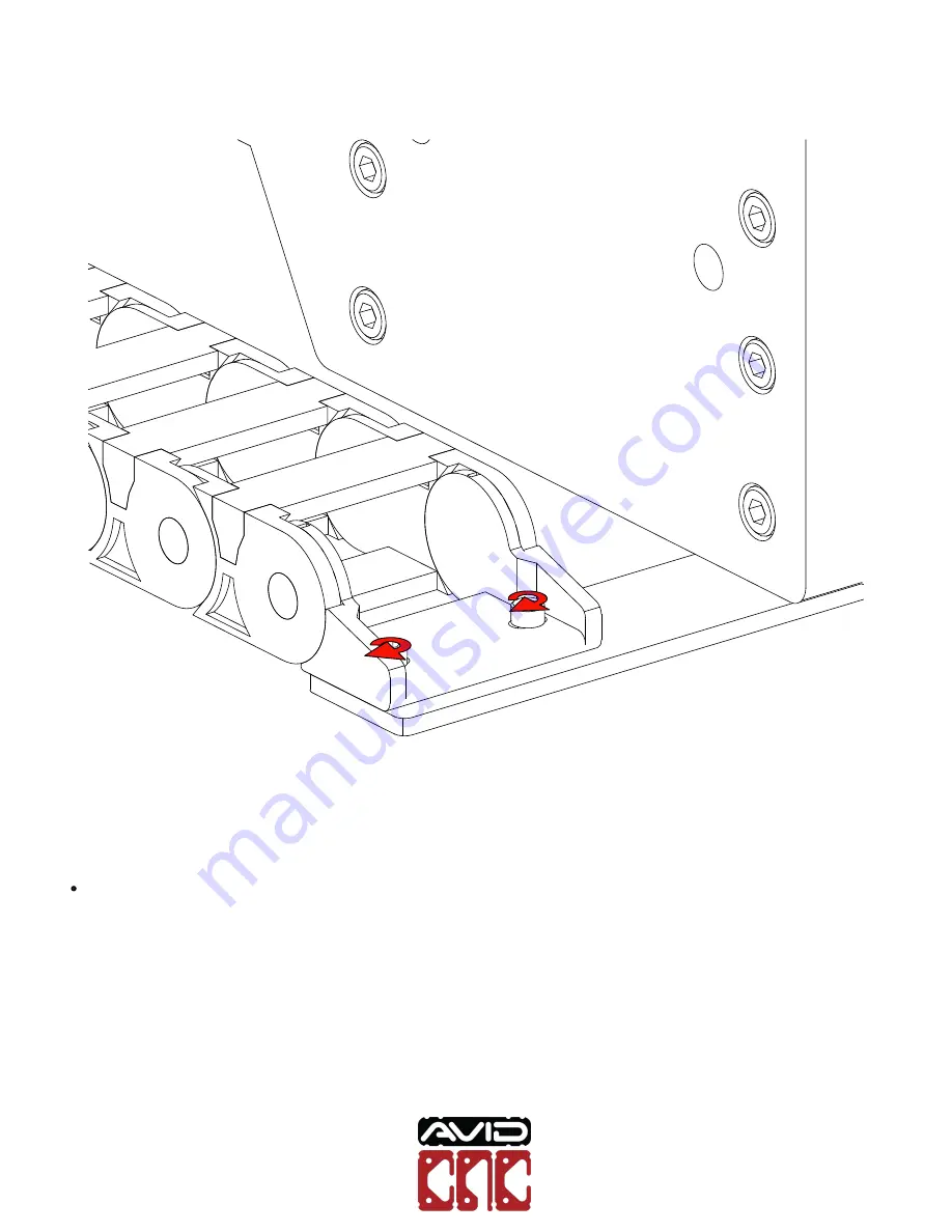
Tighten the fixed end to the lower bracket.
Benchtop PROAssembly Instructions
Version 2020Q2.1
© 2020 Avid CNC
All Rights Reserved
Page 1: ...Benchtop PRO Machine Kit Assembly Instructions Version 2020Q2 1...
Page 2: ...he larger components such as the base and optional leg kit is made easier with two people Though not required this can make the process more efficient 7 Listed below are three types of notes you will...
Page 3: ...Roll in T Nuts Assembly steps will depict Roll in T Nut installation as shown above Benchtop PRO Assembly Instructions Version 2020Q2 1 2020 Avid CNC All Rights Reserved...
Page 4: ...To install in the appropriate extrusion slot position the T Nut as indicated Benchtop PRO Assembly Instructions Version 2020Q2 1 2020 Avid CNC All Rights Reserved...
Page 5: ...Insert the T Nut into the extrusion slot and rotate 90 Benchtop PRO Assembly Instructions Version 2020Q2 1 2020 Avid CNC All Rights Reserved...
Page 6: ...ill be parallel with the face of the extrusion Assembly Note A small allen wrench can be inserted into the hole of the T Nut and subsequently used to rotate it the full 90 Benchtop PRO Assembly Instru...
Page 7: ...6mm Adjustable Wrench Standard Flat Tip Screwdriver Tape Measure Additional recommended tools and supplies 6mm Hex Ball end Power Bit and Drill Impact Driver Metric Combination Wrenches 17mm Metric T...
Page 8: ...Section 1 Table Assembly Benchtop PRO Assembly Instructions Version 2020Q2 1 2020 Avid CNC All Rights Reserved...
Page 9: ...nd Plate Total QTY 4 2 M8 x 30mm Socket Head Cap Screw Total QTY 8 2 M8 Roll In T Nut Total QTY 8 2 x 3 Parts List QTY Part Description Packaged In 4 8080 Crossmember Extrusion 641mm 25 1 4 Linear Ext...
Page 10: ...0 00 36 FAST CRP900 00 3636 HW 32 40 Series Anchor Fastener 32 M8 x 30mm Socket Head Cap Screw 16 M8 Slide in T Nut 4 CRP913 00 CRP900 00 3636 HW 1 M12 Leveling Foot 50mm Total QTY 4 1 M12 BTP Levelin...
Page 11: ...ert socket head cap screws into anchor fasteners as indicated M8 x 25mm Socket Head Cap Screw 40 Series Anchor Fastener 8080 Crossmember Extrusion Benchtop PRO Assembly Instructions Version 2020Q2 1 2...
Page 12: ...1 1 2 Slide the anchor fasteners and screws into the extrusion counterbores Benchtop PRO Assembly Instructions Version 2020Q2 1 2020 Avid CNC All Rights Reserved...
Page 13: ...1 1 3 Thread the screws into the left table ballscrew axis as indicated CRP840 00 Ballscrew Axis Left Benchtop PRO Assembly Instructions Version 2020Q2 1 2020 Avid CNC All Rights Reserved...
Page 14: ...1 1 4 Alternately you can use the provided slide in t nuts to lower the crossmember extrusion M8 Slide In T Nut Benchtop PRO Assembly Instructions Version 2020Q2 1 2020 Avid CNC All Rights Reserved...
Page 15: ...1 1 5 Tighten the indicated fasteners Assembly Note Be sure to tighten all four crossmember fasteners Benchtop PRO Assembly Instructions Version 2020Q2 1 2020 Avid CNC All Rights Reserved...
Page 16: ...previous steps to install the remaining crossmembers Machine Configuration Options 2 x 2 machines only require three crossmembers Benchtop PRO Assembly Instructions Version 2020Q2 1 2020 Avid CNC All...
Page 17: ...fasteners and screws to the other side of the extrusion and attach the right table ballscrew axis CRP840 00 Ballscrew Axis Right Benchtop PRO Assembly Instructions Version 2020Q2 1 2020 Avid CNC All...
Page 18: ...1 1 8 Tighten all remaining crossmember anchor screws Benchtop PRO Assembly Instructions Version 2020Q2 1 2020 Avid CNC All Rights Reserved...
Page 19: ...in T Nut CRP913 01 Foot Plate M8 x 20mm Socket Head Cap Screw Assembly Note If you assembled the crossmembers in the lowered configuration locate the block to the side of the crossmember rather than u...
Page 20: ...bottom of the extrusion Tighten the indicated fasteners Assembly Note If your crossmembers are not in the default configuration do not attempt to bring the foot plate flush with the extrusion Benchto...
Page 21: ...all the lock nut onto the leveling foot and thread the leveling foot into the foot plate M12 Hex Nut 7038 M12 Leveling Foot Benchtop PRO Assembly Instructions Version 2020Q2 1 2020 Avid CNC All Rights...
Page 22: ...1 2 4 Tighten the lock nut Benchtop PRO Assembly Instructions Version 2020Q2 1 2020 Avid CNC All Rights Reserved...
Page 23: ...1 2 5 Repeat this process to install the remaining leveling feet at the indicated locations Benchtop PRO Assembly Instructions Version 2020Q2 1 2020 Avid CNC All Rights Reserved...
Page 24: ...Section 2 Gantry Installation Benchtop PRO Assembly Instructions Version 2020Q2 1 2020 Avid CNC All Rights Reserved...
Page 25: ...0 XXXX HW 16 M8 x 25mm Flat Head Screw 16 M8 x 25mm Socket Head Cap Screw 16 M8 Slide in T Nut 3 Wide Parts List QTY Part Description Packaged In 1 8016 Gantry Extrusion 1120mm 44 1 16 Linear Extrusio...
Page 26: ...Required Tools 3mm Allen Wrench 5mm Allen Wrench 6mm Allen Wrench Tape Measure Benchtop PRO Assembly Instructions Version 2020Q2 1 2020 Avid CNC All Rights Reserved...
Page 27: ...2 1 Gantry Riser Assembly 2 1 1 Slide slide in T Nuts onto the right table axis as indicated M8 Slide in T Nut Benchtop PRO Assembly Instructions Version 2020Q2 1 2020 Avid CNC All Rights Reserved...
Page 28: ...2 1 2 Attach the right gantry riser to the extrusion CRP920 01 R Right Gantry Riser Benchtop PRO Assembly Instructions Version 2020Q2 1 2020 Avid CNC All Rights Reserved...
Page 29: ...2 1 3 Thread socket head cap screws into the T Nuts M8 x 25 Socket Head Cap Screw Benchtop PRO Assembly Instructions Version 2020Q2 1 2020 Avid CNC All Rights Reserved...
Page 30: ...2 1 4 Tighten the indicated bolts Benchtop PRO Assembly Instructions Version 2020Q2 1 2020 Avid CNC All Rights Reserved...
Page 31: ...2 1 5 Repeat the previous steps to attach the second gantry riser to the left table axis Benchtop PRO Assembly Instructions Version 2020Q2 1 2020 Avid CNC All Rights Reserved...
Page 32: ...2 1 6 Slide t nuts into gantry extrusion M8 Slide in T Nut 8016 Gantry Extrusion Benchtop PRO Assembly Instructions Version 2020Q2 1 2020 Avid CNC All Rights Reserved...
Page 33: ...2 1 7 Slide the risers to the back of the machine Benchtop PRO Assembly Instructions Version 2020Q2 1 2020 Avid CNC All Rights Reserved...
Page 34: ...2 1 8 Turn the machine onto its back Benchtop PRO Assembly Instructions Version 2020Q2 1 2020 Avid CNC All Rights Reserved...
Page 35: ...steners T Nuts on this face 8016 Gantry Extrusion M8 x 25mm Socket Head Cap Screw Assembly Note Orient gantry extrusion with the previously installed t nuts on the indicated face Benchtop PRO Assembly...
Page 36: ...2 1 10 Tighten the indicated bolts Benchtop PRO Assembly Instructions Version 2020Q2 1 2020 Avid CNC All Rights Reserved...
Page 37: ...ng plate to the gantry ballscrew axis CRP840 00 Ballscrew Axis Gantry M5 x 14mm Flat Head Screw Assembly Note Place these screws aside you will be reinstalling the moving plate in a future step Bencht...
Page 38: ...he moving plate and set aside Assembly Note Some force may be required to remove the moving plate from the gantry ballscrew axis Benchtop PRO Assembly Instructions Version 2020Q2 1 2020 Avid CNC All R...
Page 39: ...2 2 3 Remove the metal dust cover screws from the gantry axis and set them aside M4 x 8mm Socket Head Cap Screw Benchtop PRO Assembly Instructions Version 2020Q2 1 2020 Avid CNC All Rights Reserved...
Page 40: ...2 2 4 Remove the metal dust covers from the gantry axis Benchtop PRO Assembly Instructions Version 2020Q2 1 2020 Avid CNC All Rights Reserved...
Page 41: ...r mount plate on the indicated side Motor Mount Plate M8 x 25mm Flat Head Screw Assembly Note For all gantry sizes the two countersunk holes closest to the motor mount plate do not receive fasteners B...
Page 42: ...or mount plate is 38mm 1 1 2 from the riser 38mm 1 1 2 Machine Configuration Options For 24 gantries position the plate 46mm 1 13 16 from the riser Benchtop PRO Assembly Instructions Version 2020Q2 1...
Page 43: ...2 2 7 Tighten the gantry axis bolts Benchtop PRO Assembly Instructions Version 2020Q2 1 2020 Avid CNC All Rights Reserved...
Page 44: ...2 2 8 Slide the metal dust covers back on the gantry axis as indicated Dust Cover removed in previous step Benchtop PRO Assembly Instructions Version 2020Q2 1 2020 Avid CNC All Rights Reserved...
Page 45: ...2 2 9 Attach the metal dust covers using the screws removed in previous steps M4 x 8mm Socket Head Cap Screw Benchtop PRO Assembly Instructions Version 2020Q2 1 2020 Avid CNC All Rights Reserved...
Page 46: ...2 10 Attach the moving plate to the gantry axis using the screws removed in previous steps M5 x 14mm Flat Head Screw Benchtop PRO Assembly Instructions Version 2020Q2 1 2020 Avid CNC All Rights Reserv...
Page 47: ...Section 3 Z Axis Installation Benchtop PRO Assembly Instructions Version 2020Q2 1 2020 Avid CNC All Rights Reserved...
Page 48: ...Description Packaged In 1 CRP840 00 200 PRO Linear Ballscrew Axis Z Axis 1 CRP940 00 FAST CRP900 00 XXXX HW 8 M8 x 25mm Flat Head Screw 8 M8 Slide in T Nut Required Tools 3mm Allen Wrench 5mm Allen Wr...
Page 49: ...3 1 Z Axis Installation 3 1 1 Remove the moving plate from the Z axis M5 x 14mm Flat Head Screw Benchtop PRO Assembly Instructions Version 2020Q2 1 2020 Avid CNC All Rights Reserved...
Page 50: ...3 1 2 Remove the metal dust cover screws from the Z axis and set them aside M4 x 8mm Socket Head Cap Screw Benchtop PRO Assembly Instructions Version 2020Q2 1 2020 Avid CNC All Rights Reserved...
Page 51: ...3 1 3 Remove the metal dust covers from the Z Axis Benchtop PRO Assembly Instructions Version 2020Q2 1 2020 Avid CNC All Rights Reserved...
Page 52: ...lide the M8 T Nuts into the gantry plate and install the Z axis to the gantry M8 x 25mm Flat Head Screw M8 Slide in T Nut Benchtop PRO Assembly Instructions Version 2020Q2 1 2020 Avid CNC All Rights R...
Page 53: ...3 1 5 Tighten the indicated bolts Benchtop PRO Assembly Instructions Version 2020Q2 1 2020 Avid CNC All Rights Reserved...
Page 54: ...3 1 6 Slide the metal dust covers back on the Z axis as indicated Dust Cover removed in previous step Benchtop PRO Assembly Instructions Version 2020Q2 1 2020 Avid CNC All Rights Reserved...
Page 55: ...3 1 7 Attach the metal dust covers using the screws removed in previous steps M4 x 8mm Socket Head Cap Screw Benchtop PRO Assembly Instructions Version 2020Q2 1 2020 Avid CNC All Rights Reserved...
Page 56: ...3 1 8 Attach the moving plate to the Z axis using the screws removed in previous steps M5 x 14mm Flat Head Screw Benchtop PRO Assembly Instructions Version 2020Q2 1 2020 Avid CNC All Rights Reserved...
Page 57: ...Section 4 Motor Installation Benchtop PRO Assembly Instructions Version 2020Q2 1 2020 Avid CNC All Rights Reserved...
Page 58: ...er Motor Electronics 1 CRP900 00 MOTOR HW 375 CRP900 00 XXXX HW 4 Oldham Assembly Motor Side 16 M5 x 12mm Socket Head Cap Screw Required Tools 4mm Allen Wrench 3mm Allen Wrench Tape Measure Section No...
Page 59: ...tallation 4 1 1 Slide the motor side of the oldham coupler onto the motor as indicated NEMA 23 Motor Oldham Assembly Motor Half Benchtop PRO Assembly Instructions Version 2020Q2 1 2020 Avid CNC All Ri...
Page 60: ...4 1 2 Position the end of the coupler 26mm 1 1 32 from the motor flat 26mm 1 1 32 Benchtop PRO Assembly Instructions Version 2020Q2 1 2020 Avid CNC All Rights Reserved...
Page 61: ...4 1 3 Tighten the clamp bolt as indicated Benchtop PRO Assembly Instructions Version 2020Q2 1 2020 Avid CNC All Rights Reserved...
Page 62: ...4 1 4 Attach the motor to one of the table axes as indicated M5 x 10mm Socket Head Cap Screw NEMA 23 Motor Benchtop PRO Assembly Instructions Version 2020Q2 1 2020 Avid CNC All Rights Reserved...
Page 63: ...4 1 5 Tighten the indicated fasteners Benchtop PRO Assembly Instructions Version 2020Q2 1 2020 Avid CNC All Rights Reserved...
Page 64: ...4 1 6 Install motors on the remaining axes Slaved Motor Y Motor X Motor Z Motor Benchtop PRO Assembly Instructions Version 2020Q2 1 2020 Avid CNC All Rights Reserved...
Page 65: ...epper Motor Motors 1 CRP900 00 MOTOR HW 500 CRP900 00 XXXX HW 4 Oldham Assembly Motor Side 16 M6 x 16mm Socket Head Cap Screw Required Tools 3mm Allen Wrench 5mm Allen Wrench Tape Measure Section Note...
Page 66: ...tallation 4 2 1 Slide the motor side of the oldham coupler onto the motor as indicated NEMA 34 Motor Oldham Coupler Motor Half Benchtop PRO Assembly Instructions Version 2020Q2 1 2020 Avid CNC All Rig...
Page 67: ...flat Then tighten the clamping screw on the oldham coupler 30mm 1 3 16 Assembly Note The dimension shown is measured from the boss on the motor to the top of the oldham coupler Benchtop PRO Assembly...
Page 68: ...4 2 3 Attach the motor to one of the table axes as indicated NEMA 34 Motor M6 x 16mm Socket Head Cap Screw Benchtop PRO Assembly Instructions Version 2020Q2 1 2020 Avid CNC All Rights Reserved...
Page 69: ...4 2 4 Tighten the indicated fasteners Benchtop PRO Assembly Instructions Version 2020Q2 1 2020 Avid CNC All Rights Reserved...
Page 70: ...4 2 5 Install motors on the remaining axes Slaved Motor Y Motor X Motor Z Motor Benchtop PRO Assembly Instructions Version 2020Q2 1 2020 Avid CNC All Rights Reserved...
Page 71: ...Section 5 Cable Track Installation Benchtop PRO Assembly Instructions Version 2020Q2 1 2020 Avid CNC All Rights Reserved...
Page 72: ...00 XX 2 50mm Cable Track Section CRP950 00 XX 1 CRP950 00 FAST CRP950 00 XX 6 M8 Roll in T Nut 4 M8 x 16mm Socket Head Cap Screw 4 M5 x 12mm Socket Head Cap Screw 2 M8 x 30mm Socket Head Cap Screw 2...
Page 73: ...stall the lower cable track bracket onto the bottom of the base of the machine M8 Roll in T Nut CRP950 01 Cable Track Bracket M8 x 16mm Socket Head Cap Screw Benchtop PRO Assembly Instructions Version...
Page 74: ...rom the front of the machine 647mm 25 Machine Configuration Option For 2 length machines position the bracket 380mm 15 from the front of the machine Benchtop PRO Assembly Instructions Version 2020Q2 1...
Page 75: ...5 1 3 Tighten the indicated fasteners Benchtop PRO Assembly Instructions Version 2020Q2 1 2020 Avid CNC All Rights Reserved...
Page 76: ...Install the upper cable track bracket M8 Roll in T Nut M8 x 16mm Socket Head Cap Sccrew CRP950 02 Cable Track Bracket Benchtop PRO Assembly Instructions Version 2020Q2 1 2020 Avid CNC All Rights Rese...
Page 77: ...ck to the bracket as indicated M5 x 12mm Socket Head Cap Screw Assembly Note The fixed end of the cable track is the one which does not rotate independently Benchtop PRO Assembly Instructions Version...
Page 78: ...5 1 6 Tighten the fixed end to the lower bracket Benchtop PRO Assembly Instructions Version 2020Q2 1 2020 Avid CNC All Rights Reserved...
Page 79: ...5 1 6 Attach the other end to the upper bracket M5 x 12mm Socket Head Cap Screw Cable Track Free End Benchtop PRO Assembly Instructions Version 2020Q2 1 2020 Avid CNC All Rights Reserved...
Page 80: ...5 1 8 Tighten the end to the upper bracket Benchtop PRO Assembly Instructions Version 2020Q2 1 2020 Avid CNC All Rights Reserved...
Page 81: ...5 1 9 Tighten upper bracket to the gantry extrusion Benchtop PRO Assembly Instructions Version 2020Q2 1 2020 Avid CNC All Rights Reserved...
Page 82: ...ts into the provided anchors and place the anchors in the bracket extrusion provided M8 x 30mm Socket Head Cap Screw CRP950 03 4040 Cable Track Extrusion 40 Series Anchor Fastener Benchtop PRO Assembl...
Page 83: ...5 2 2 Slide the anchors into the cable track extrusion as indicated Benchtop PRO Assembly Instructions Version 2020Q2 1 2020 Avid CNC All Rights Reserved...
Page 84: ...5 2 3 Attach the cable track extrusion to the Z axis indicated M8 Roll in T Nut Benchtop PRO Assembly Instructions Version 2020Q2 1 2020 Avid CNC All Rights Reserved...
Page 85: ...5 2 4 Position the bracket extrusion approximately 25mm 1 from the top of the Z axis 25mm 1in Benchtop PRO Assembly Instructions Version 2020Q2 1 2020 Avid CNC All Rights Reserved...
Page 86: ...5 2 5 Tighten the cable track extrusion fasteners as indicated Benchtop PRO Assembly Instructions Version 2020Q2 1 2020 Avid CNC All Rights Reserved...
Page 87: ...fixed end of a length of cable track to the gantry extrusion M5 Roll in T Nut Cable Track Fixed End M5 x 16mm Socket Head Cap Screw Benchtop PRO Assembly Instructions Version 2020Q2 1 2020 Avid CNC Al...
Page 88: ...1 from the riser plate 280mm 11 Machine Configuration Option For the 3 width machines position the cable track approximately 530mm 21 from the end of the riser plate Benchtop PRO Assembly Instructions...
Page 89: ...5 2 8 Tighten the fixed end in place Benchtop PRO Assembly Instructions Version 2020Q2 1 2020 Avid CNC All Rights Reserved...
Page 90: ...Install the free end onto the extrusion bracket M5 x 16mm Socket Head Cap Screw Cable Track Free End M5 Roll in T Nut Benchtop PRO Assembly Instructions Version 2020Q2 1 2020 Avid CNC All Rights Rese...
Page 91: ...5 2 10 Tighten the free end in place Benchtop PRO Assembly Instructions Version 2020Q2 1 2020 Avid CNC All Rights Reserved...
Page 92: ...Section 6 Tabletop Extrusion Installation Benchtop PRO Assembly Instructions Version 2020Q2 1 2020 Avid CNC All Rights Reserved...
Page 93: ...iption Packaged In 8 8020 720 CS6 T Slot Machine Table Extrusion CRP8020 720 CS6 BT 2436 1 CRP8020 720 CS6 BT 2436 FAST CRP8020 720 CS6 BT 2436 64 M5 x 16mm Flat Head Screw 64 M5 Roll in T Nut 3 x 3 P...
Page 94: ...1 Attach a piece of tabletop extrusion to the machine crossmembers as indicated 8020 Table Extrusion M5 Roll in T Nut M5 x 16mm Flat Head Screw Benchtop PRO Assembly Instructions Version 2020Q2 1 2020...
Page 95: ...6 1 2 Partially tighten the tabletop extrusion fasteners Benchtop PRO Assembly Instructions Version 2020Q2 1 2020 Avid CNC All Rights Reserved...
Page 96: ...6 1 3 Repeat the previous steps to install the remaining tabletop extrusion pieces Benchtop PRO Assembly Instructions Version 2020Q2 1 2020 Avid CNC All Rights Reserved...
Page 97: ...6 1 4 Fully tighten the tabletop extrusion fasteners Benchtop PRO Assembly Instructions Version 2020Q2 1 2020 Avid CNC All Rights Reserved...
Page 98: ...Section 7 Motor and Sensor Connections Benchtop PRO Assembly Instructions Version 2020Q2 1 2020 Avid CNC All Rights Reserved...
Page 99: ...7 1 Motor and Sensor Locations 7 1 1 Y Z X Y Z X Benchtop PRO Assembly Instructions Version 2020Q2 1 2020 Avid CNC All Rights Reserved...
Page 100: ...7 1 2 Y Switch X Switch Slaved Switch Z Switch X Switch Y Switch Benchtop PRO Assembly Instructions Version 2020Q2 1 2020 Avid CNC All Rights Reserved...
Page 101: ...7 1 3 Slaved Motor Y Motor X Motor Z Motor Benchtop PRO Assembly Instructions Version 2020Q2 1 2020 Avid CNC All Rights Reserved...
Page 102: ...r Directly to control box X Switch Through table cable track X Switch Across gantry and through table cable track X Motor Through table cable track Z Motor Through table cable track and gantry cable t...
Page 103: ...ugh cable track Assembly Note The X sensor cable is routed on top of the gantry but not inside the gantry cable track Assembly Note If using an Avid CNC Plug and Play CNC Control System purchased afte...
Page 104: ...Cables Axis Color Cable X Motor Green 12 X Sensor Blue 12 X Sensor Purple 20 Z Motor Red 20 Z Sensor Yellow 20 Benchtop PRO Assembly Instructions Version 2020Q2 1 2020 Avid CNC All Rights Reserved...
Page 105: ...To route cables through the cable track use a screwdriver to lift open the individual cable track sections as indicated Benchtop PRO Assembly Instructions Version 2020Q2 1 2020 Avid CNC All Rights Res...
Page 106: ...ption Packaged In 1 Proximity Sensor Kit Electronics 6 Cylindrical Proximity Sensors Proximity Cables See table in Step 7 2 2 for lengths Required Tools Adjustable Wrench Tape Measure Recommended Addi...
Page 107: ...7 1 2 M12 x 1 0 Hex Jam Nut Included with sensor Z Sensor 22mm 7 8 Assembly Note We recommend positioning the sensors 22mm 7 8 from the inside of the Motor Mount Plate as indicated Benchtop PRO Assem...
Page 108: ...Section 8 Machine Setup Benchtop PRO Assembly Instructions Version 2020Q2 1 2020 Avid CNC All Rights Reserved...
Page 109: ...lectronics 4 The next step to get your machine up and running will be to setup your CNC software Our CNC Software Setup Guide https www avidcnc com support software provides step by step instructions...