


7
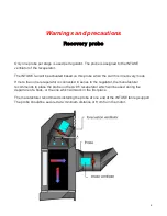
Warnings and precautions
DPDT relay used for defrost cycles in
Maximus
and
AVI-28
The controller switch corresponding to the relay energizing the DPDT contactors (not included)
is automatically deactivated to prevent human error. Automatic deactivation of the switch
prevents undesired fan rotation inversions caused by the user.
DPDT contactors are energized only automatically by the controller.
Automatic Reversal of
INTAKE
Fan Rotation will not occur if the variable board switch
associated with the
INTAKE
fans is not set to automatic position.
The manufacturer recommends to check the reversal of rotation functions of the INTAKE fan at
the first start of the Avi35.
INTERLOCK double relays used for defrost cycles in
Multi-Zone
Genius
The GENIUS controller will used two relays to energize the corresponding interlock double
relay contactors (not included) that activates the defrost cycles. Therefore, the first relay will
activate the fan clockwise, whereas the second relay will activate the fan counterclock wise.
The manufacturer recommends to check the reversal of rotation functions of the INTAKE fan at
the first start of the Avi35.
Summary of Contents for AVI35
Page 1: ...Installation and User Manual...
Page 2: ...2...
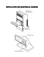
Page 10: ...10 INSTALLATION AND ELECTRICLAL DIAGRAM...
Page 11: ...11 INSTALLATION AND ELECTRICLAL DIAGRAM...
Page 12: ...12 Maximus AVI 28 CONNECTION DIAGRAM...
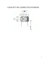
Page 14: ...14 EXHAUST FAN CONNECTION DIAGRAM...
Page 15: ...15 INTAKE FAN CONNECTION DIAGRAM...
Page 16: ...16 Installation Guide...
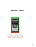
Page 18: ...18 Installation diagram 1...
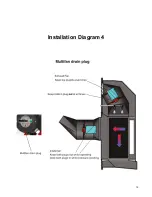
Page 19: ...19 Installation Diagram 4...