AVI-AIR AVI35 Installation And User Manual Download Page 17


17 


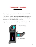
Warnings and precautions 


The manufacturer recommends installing the recuperators in the wall of the building. Ideally, 
the Avi35 should not be installed directly above each other to prevent ice build-up above the 
unit on the lower floor. Also, plan for a large accumulation of ground ice at the exit of the 
recuperator during winter.


The manufacturer also recommends that a distance of at least 7 meters be maintained 
between the Avi35 recuperator and another standard building exhaust fan. The aim is to 
prevent a return of stale and dusty air from other standard exhaust fans in the Avi35 fresh air 
INTAKEs. 


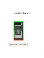
Do not drill holes in the bottom of the Avi35

. See installation diagram 1 


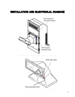
Secure the unit to the wall by aiming through the pre-drilled holes in the facade. Screw both 
sides of the unit into the wall frame. See installation diagram 3. 
 
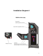
Refer to diagram 4 regarding the drain plugs on Multifan fan motors


Summary of Contents for AVI35

Page 1: ...Installation and User Manual...

Page 2: ...2...

Page 3: ...take Ventilator 1 60Hz 240V 1 9A RPM 3255 CSA 172512 Exhaust Ventilator 1 60Hz 240V 1 9A RPM 3255 CSA 172512 Patent Pending USPTO 62 366 657 www distributionavi air com 114 Rang Roy 450 375 5539 Saint...

Page 4: ...4 Table of content Electrician s note and diagram Page 5 Installation Guide Page 17 Warranty Page 21...

Page 5: ...5 Electrician s Notes and Connection Diagram The manufacturer recommends that the electrical connection be performed by a qualified electrician...

Page 6: ...is in recovery mode If more than one recuperator is connected in series to the regulator the manufacturer recommends to place the probe on the Avi35 recuperator which will be used during the departur...

Page 7: ...board switch associated with the INTAKE fans is not set to automatic position The manufacturer recommends to check the reversal of rotation functions of the INTAKE fan at the first start of the Avi35...

Page 8: ...t included providing a minimum of 10 gpm at 50 psi to provide sufficient water to the flushing system All regulators in the same building use the same centrifugal booster pump Each solenoid valve 240V...

Page 9: ...ithout touching the electrical wire See diagram The INTAKE VENTILATORS must be connected in parallel to another variable relay of the regulator Drill the upper right corner of the inlet fan housing to...

Page 10: ...10 INSTALLATION AND ELECTRICLAL DIAGRAM...

Page 11: ...11 INSTALLATION AND ELECTRICLAL DIAGRAM...

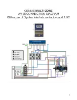
Page 12: ...12 Maximus AVI 28 CONNECTION DIAGRAM...

Page 13: ...13 GENIUS MULTI ZONE AVI35 CONNECTION DIAGRAM With a pair of 3 poles interlock contactors and 1 NC...

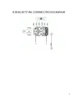
Page 14: ...14 EXHAUST FAN CONNECTION DIAGRAM...

Page 15: ...15 INTAKE FAN CONNECTION DIAGRAM...

Page 16: ...16 Installation Guide...

Page 17: ...o recommends that a distance of at least 7 meters be maintained between the Avi35 recuperator and another standard building exhaust fan The aim is to prevent a return of stale and dusty air from other...

Page 18: ...18 Installation diagram 1...

Page 19: ...19 Installation Diagram 4...

Page 20: ...ny modification and repair not authorized by the manufacturer on this product automatically void the warranty and relieves the manufacturer of any liability The manufacturer assumes only the aforement...

Reviews: