


Operator Controls
Power Switch
Controls printer power
On-normal operation
Off-the power should be turned off before connect or disconnect
the communication cables and power cables
Feed Button
Advance the label media to first printing position
Press-to advance a label
Press-takes the printer out of a "pause" condition
Press-back feed the label to correct label installation, in case that
label is not properly installed. (for OS-202 Peel-Off mode only)
Keep pressing while turning on the power- to print out a
configuration profile
Ready Indicator
Show the printers status
Green-printer is ready to operate
Blinking-printer is paused
Power indicator
Shows the power and error status
Off-printer power off
Green-printer power on
Blinking-error occurs
26
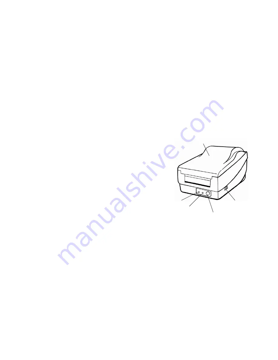
Power Indicator
Ready Indicator
Power Switch
Top Cover
Feed Button
25


