


USER MANUAL
5
M
M
a
a
k
k
i
i
n
n
g
g
t
t
h
h
e
e
C
C
o
o
n
n
n
n
e
e
c
c
t
t
i
i
o
o
n
n
s
s
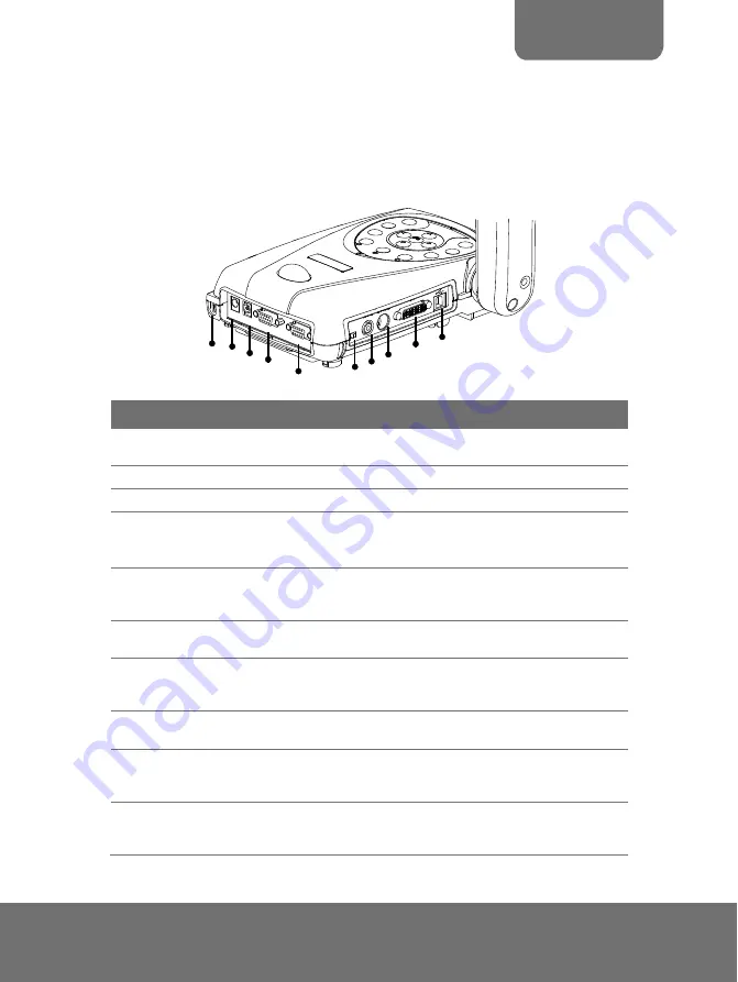
The ports on the rear and left panel of the AVerVisi enable you to connect the
unit to a computer, graphics display monitor or LCD/DLP projector, TV or other device.
Illustrated below are the ports that are located at the rear and left panel of the
AVerVisi with their corresponding labels.
TV R
GB
VID
EO
S-V
IDE
O
DVI
(2)(3)
(4)
(5)
(6)(7)
(8)
(1)
(9)
(10)
VGAO
UT
VGAIN
DC12V
LIGHT
BOX
Port
Description
(1) Antitheft Slot
Attach a Kensington compatible security lock or antitheft
device.
(2) DC 12V (input)
Connect the power adapter into this port.
(3) Light Box Port
Plug the optional light box into this port.
(4) VGA IN Port
Input the VGA signal from a computer or other sources
and actively pass it through to the VGA output port only.
Connect this port to the VGA output port of the computer.
(5) VGA OUT Port
Output the VGA signal from the camera, VGA input port, or
the captured images from the memory on a VGA/Mac
monitor or LCD/DLP projector.
(6) TV/RGB Switch
Set to select the between RGB (VGA Out) or TV
(Composite Video/S-Video Out) display output.
(7) VIDEO Port
(RCA/Composite)
Output the video signal from the camera or the captured
images from the built-in memory on TV or video
equipment.
(8) S-VIDEO Port
Output the video signal from the camera or the captured
images from the memory on TV or video equipment.
(9) DVI Port
Output the video signal from the camera, or the captured
images from the memory on an LCD monitor or LCD/DLP
projector with DVI interface.
(10) USB Port
Use AVerVisi as a USB Camera or Image
Download allowing you to transfer the captured images to
and from the AVerVisi built-in memory and PC.
Summary of Contents for AVerVision300AF+
Page 1: ...AVerVision300AF USER MANUAL ...
Page 2: ...P N 300AP0E3 DPK M a d e i n Ta i wa n ...
Page 6: ......


