


www.avenview.com|10
1.10
Operation and IR Control
1.10.1 Method A: Push Button
1.
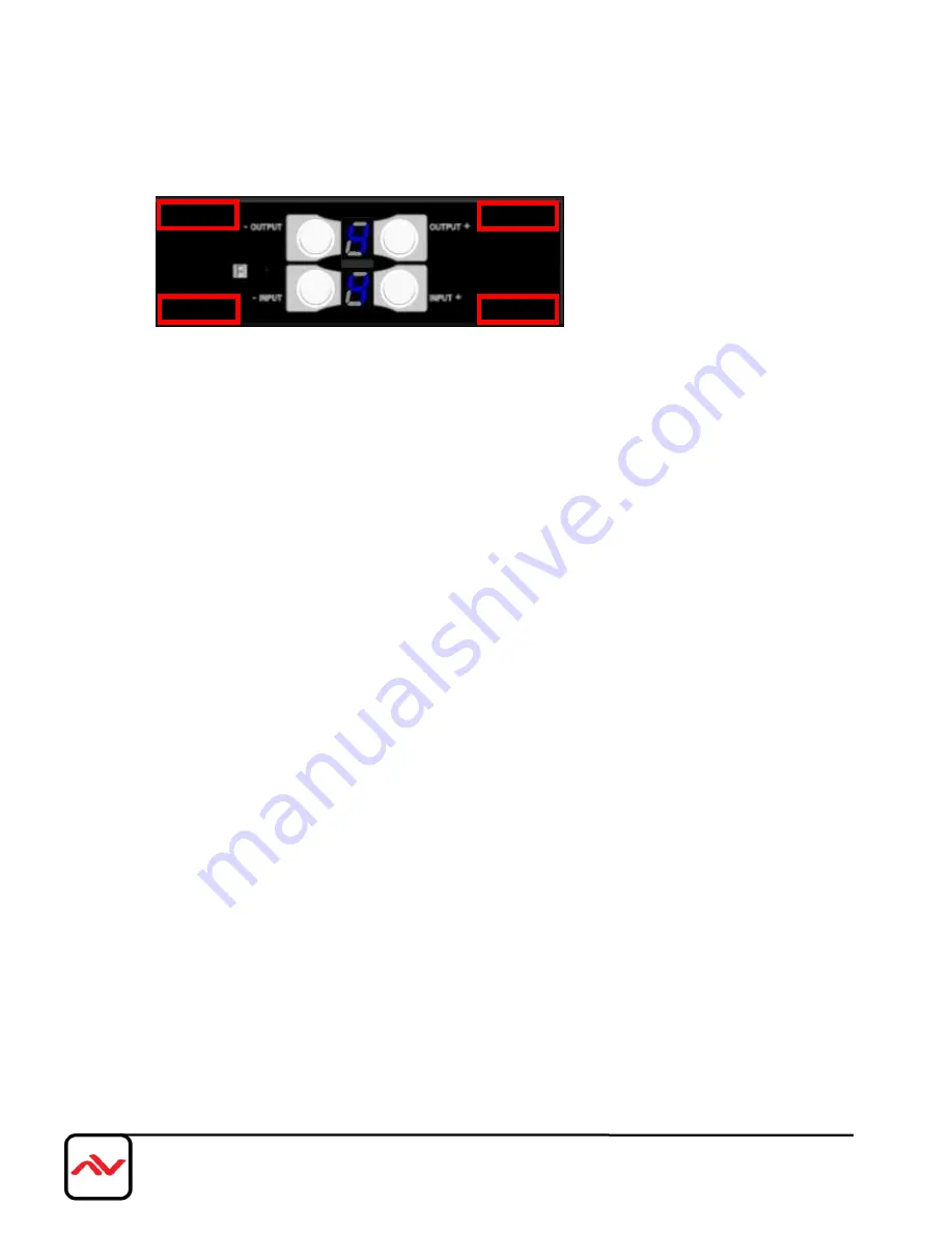
IN/OUT MAP
1)
Use the “+”or “-“ output push button to select the number of display
2)
Use the “+”or “-“ input push button to select the number of input source
“+”: change selected input/output port in ascending order
“-” : change selected input/output port in descending order
After you select the desired input/output port, the LED will blink twice and the setting will be effective
2.
Save Mapping Mode
1)
Keep pushing “ (save)”button until the output LED shows “d.” to enter the Save Mapping Mode.
2)
Use the “+”or “-“ input push button to select the mapping configuration (0~7) which you want to save
current input/output mapping
3)
After you select the desired mapping configuration number, the LED will blink twice and the mapping
setting will be saved
4)
If you push the “output- (preset)”button before the mapping setting is saved, the LED will show
“
一
”“
一
”to quit the Save Mapping Mode
3.
Preset Mapping Mode
1)
Keep pushing “output- (preset)”button until the output LED shows “P.” to enter the Preset Mapping
Mode.
2)
Use the “+”or “-“ input push button to select the saved mapping configuration (0~7) which you want to
recall
3)
After you select the desired mapping configuration number, the LED will blink twice and the mapping
setting will be effective
4)
If you push the “ (save)”button before the mapping setting is effective, the LED will show
“
一
”“
一
”to quit the Preset Mapping Mode
Default
Learn
Preset
Save


