background image

Table of Contents

Section 1: Getting Started

 ......................................................................................................................1


1.1   Important Safeguards

 ..............................................................................................................1


1.2   Safety Instructions

 ...................................................................................................................1


1.3   Regulatory Notices Federal Communications Commission (FCC)

 ............................................2


1.4   Introduction

 ............................................................................................................................2

     1.5   Package Contents ....................................................................................................................3


1.6   Before Installation

 ...................................................................................................................3

     1.7   Inputs and outputs ..................................................................................................................3


1.8 

Installation

 ...............................................................................................................................

4


1.8.1     Safety Precautions

 ..........................................................................................................

4


1.8.2     Installation Precautions

 ..................................................................................................5

Section 2: Specifications

 .........................................................................................................................6


2.1 

I/O Connectors

 ........................................................................................................................6


2.2 

Specifications

 ..........................................................................................................................6


2.3 

Supported Resolutions

 ............................................................................................................7


2.3.1     DVI-D IN Resolution

 ........................................................................................................7


2.3.2     VGA IN Resolution

 ..........................................................................................................7

             2.3.3     

DVI-D OUT Resolution

 ....................................................................................................7


2.4 

Control Software Instructions

 .................................................................................................8


2.4.1


System Requirement and Precautions

 ...........................................................................8


2.4.2


Software Connection

 ......................................................................................................8


2.4.3


Software Operation

 ........................................................................................................9

Summary of Contents for DVI-VIDEOWALL-4X

Page 1: ...hanges to specifications and product descriptions at any time without notice No license whether express implied or otherwise to any intellectual property rights is granted by this publication Except as set forth in Avenview Standard Terms and Conditions of Sale Avenview assumes no liability whatsoever and disclaims any express or implied warranty relating to its products of Avenview Inc is strictl...

Page 2: ...tion 3 1 7 Inputs and outputs 3 1 8 Installation 4 1 8 1 Safety Precautions 4 1 8 2 Installation Precautions 5 Section 2 Specifications 6 2 1 I O Connectors 6 2 2 Specifications 6 2 3 Supported Resolutions 7 2 3 1 DVI D IN Resolution 7 2 3 2 VGA IN Resolution 7 2 3 3 DVI D OUT Resolution 7 2 4 Control Software Instructions 8 2 4 1 System Requirement and Precautions 8 2 4 2 Software Connection 8 2 ...

Page 3: ... Instructions The DVI VIDEOWALL 4X 4 Display Dual View Cascadable Videowall Processor has been tested for conformance to safety regulations and requirements and has been certified for international use However like all electronic equipments the DVI VIDEOWALL 4X should be used with care Read the following safety instructions to protect yourself from possible injury and to minimize the risk of damag...

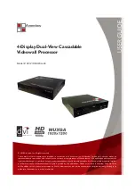
Page 4: ...e DVI VIDEOWALL 4X sends the resulting mixed video thru DVI interface to the connected monitors projectors based on the display layout The layout can be readily modified to fit your applications and optimize visual effects Typical applications include digital signage and broadcasting education surveillance systems etc Nine DVI outputs from 640x480 to 1920x1200 with a local loop out for monitoring ...

Page 5: ...orrect specifications If inappropriate power supply is used then it may cause a fire Do not twist or pull by force ends of the optical cable It can cause malfunction 1 7 Inputs and outputs The DVI VIDEOWALL 4X has five inputs HDMI DVI CVBS YPbPr VGA and accepts both graphics and video signals which come from computers and NTSC PAL video sources respectively There is a concept of main channel and s...

Page 6: ...1 8 1 Safety Precautions I To prevent fire or shock hazards do not expose this device to rain or moisture II When connecting other products such as DVD players and personal computers you should turn off the power of this product for protection against electric shocks III The product should be placed more than one foot away from heat sources such as radiators heat registers stoves and other product...

Page 7: ...unit back to dealers for service not in the original box may result in voiding warranty or additional cost Placement The unit uses convection and fans to cool Do not block the sides of this device or stack another device on the top or bottom of the DVI VIDEOWALL 4X Connections We recommend the highest quality cables for both input and output connections 1 Switch on all devices connected and then c...

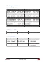
Page 8: ... Composite S video Y cable Output Connector Display DVI OUT DVI displays 2 2 Specifications Format Connectors Resolutions Inputs DVI single link RGB NTSC PAL composite and YPbPr component DVI 29 pin female x2 RGB 15 pin HD D Sub female x1 Composite RCA female x1 YPbPr Component 3 RCA female x1 640x480 to 1920x1200 pixels Outputs DVI D DVI 29 pin female x10 800x600 to 1920x1200 pixels Control RS 23...

Page 9: ...40x480 67Hz VESA 1024x768 85Hz VESA 1600x1200 60Hz HDTV 1080i 1920x1080 60Hz VESA 640x480 72Hz VESA 1152x864 75Hz VESA 1920x1200 60Hz HDTV 1080p 1920x1080 30Hz VESA 640x480 75Hz MAC 1152x870 75Hz VESA 800x600 85Hz VESA 720x400 85Hz VESA 640x480 85Hz SUN 1152x900 66Hz VESA 800x600 56Hz VESA 800x600 60Hz SUN 1152x900 76Hz VESA 800x600 72Hz VESA 800x600 75Hz VESA 1280x960 60Hz 2 3 2 VGA IN Resolution...

Page 10: ...DEOWALL 4X after you press any key on the remote control 2 4 2 Software Connection 1 Power up the DVI VIDEOWALL 4X and you can see Vacuum Fluorescent Display VFD on the front panel blinks Make sure the serial port RS 232 connection secure 2 The first step after running the software is to automatically detect if the device responses correctly through RS 232 port The process takes 5 15 seconds If th...

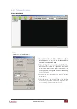
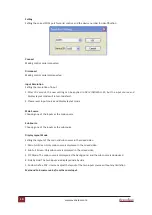
Page 11: ...setting 2 Display Setting The main and sub sources both can be adjusted to 16 9 or 4 3 The brightness and contrast of the mixed video also can be adjusted for different requirement After setting please press Update Setting to save the change 3 Firmware Ver To know the current firmware version of the device 4 Color Balance The color of the video can be automatically adjusted But it works only when ...

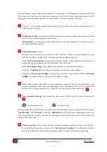
Page 12: ...ay layout mode Main Source Choosing one of the inputs as the main source Sub Source Choosing one of the inputs as the sub source Display Layout Mode Setting the layout of the main and sub sources in the mixed video 1 Main Full Screen Only main source is displayed in the mixed video 2 Sub Full Screen Only sub source is displayed in the mixed video 3 PIP Mode The main source is displayed as the back...

Page 13: ...independently setup to display any area of the input video Each output can be with different output resolutions to adapt different combinations of monitors or projectors To select each individual output to setup with preferable output please click on the desired output and the control dialog window will show up accordingly 3 4 5 6 2 1 ...

Page 14: ...omatically load the new settings into processor Clicking on Update Status will keep the information of the input video updated Clicking on Update Apply Settings will load the parameters into processor While Auto Apply Settings is checked users do not worry about settings changes 4 Define XTotal YTotal Upper left X Y point coordinates using scroll bars or manually keying in this section accordingly...

Page 15: ...www avenview com Avenview 13 ...

Page 16: ...unitive incidental or consequential damages in connection with the furnishing performance or use of the Avenview hardware software or other products and documentation provided herein Avenview Inc reserves the right to make changes without further notice to a product or system described herein to improve reliability function or design With respect to Avenview products which this document relates Av...

Reviews: